Intervertebral connection system

Inactive Publication Date: 2008-03-18
DEPUY ACROMED INC
View PDF186 Cites 196 Cited by
  • Summary
  • Abstract
  • Description
  • Claims
  • Application Information

AI Technical Summary

Benefits of technology

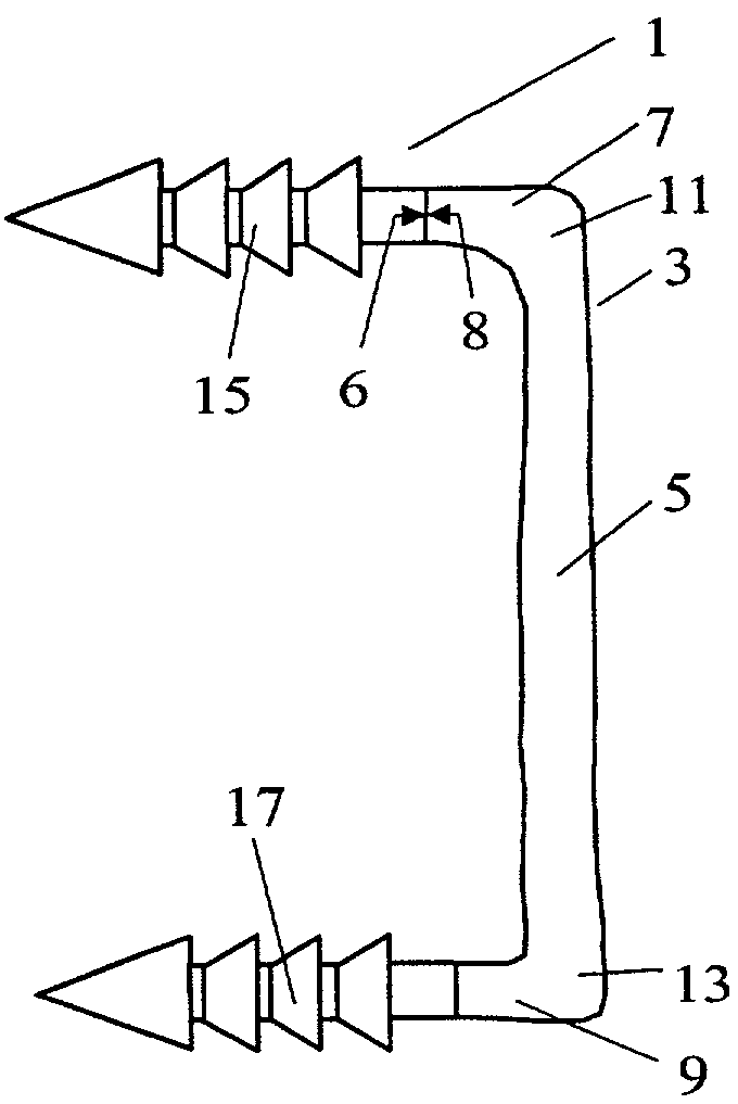
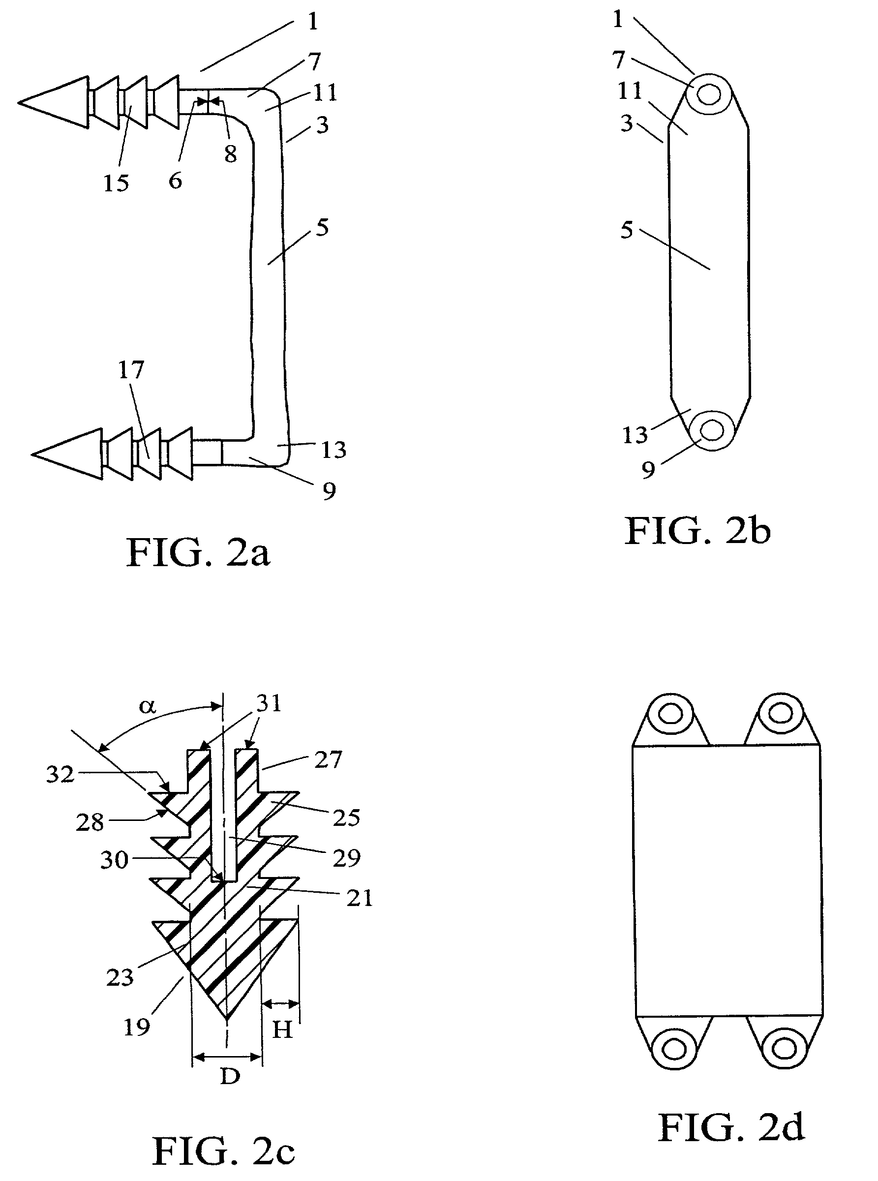
[0018]In one aspect of the present invention, the present inventors have developed a system in which a ligament has conformable portions and end portions shaped to cooperatively connect to shoulderless bone fasteners. The shoulderless feature of the bone fastener allows the bone fastener to be fully driven into the vertebral surface, thereby eliminating any problematic protrusion while also providing a means to adjust the tension of the ligament after the bone fasteners have been located. The conformable portions of the ligament allow the ligament to conform to the recess produced by a fully driven bone fastener without gener

Problems solved by technology

However, because anterior fixation, especially in the abdominal or thoracic area, lies in close proximity to vital internal organs such as the aorta, these fixation systems must also possess a low profile.
When the ligament is relatively rigid, it must essentially fully lie upon the anterior surfaces of the adjacent vertebrae, thereby limiting design options.
When the bone fastener is seated upon the vertebral surface, a portion of the bone fastener protrudes from the surface and the tension of the ligament can not be further adjusted.
Since these terminal portions 8a, 8b are relatively rigid, the ligament must essentially fully lie upon the anterior surfaces of the adjacent vertebrae, thereby limiting design options.
In addition, if the Holmes device were used for anterior fixation, its lack of control of the bone screw profile could cause the screw head to protrude towards the aorta.
Further, there is no teaching in Holmes that the ligament or screws could be bioresorbable.
Accordingly, this staple does not provide the degree of flexibility provided by a natural ligament, and so is prone to failure during compression of the spine.
Such a failure could spread device fragments about the area of the aorta and lungs.
The rigidity of the staple also hinders the loading of the interbody fusion cage, thereby producing undesirable stress shielding.
The rigidity of this staple also makes it unsuitable for use with intradiscal devices designed to provide a

Method used


Image

  • Intervertebral connection system
  • Intervertebral connection system
  • Intervertebral connection system

Examples


Example

EXAMPLE I

[0157]Now referring to FIG. 6a, a punch 61 is used to create a pair of recesses 63 on the anterior surfaces 54 of the adjacent vertebral bodies 65. These recesses are shaped to have approximately the same diameter DR as the shank diameter of the bone fastener, and a depth LR at least as deep as the length LBF of the bone fastener.

[0158]As shown in FIG. 6b, the implant of FIG. 2 is affixed to the insertion tool 51 by inserting tips 59 into the implant recesses. The arms 67 are long enough to fully bury the bone fasteners in the vertebral body recesses. Therefore, this procedure requires only two steps: punching recesses in the vertebral body, and inserting the implant, thereby making it simple and rapid. This is a very attractive feature for use in spine fusion procedures which are very lengthy. Optionally, a single tip driver (not shown) may be used to further drive one bone fastener further into the vertebral body, thereby further tensioning the ligament. The completed pro...

Example

EXAMPLE II

[0159]In this example, the implant of the present invention is applied to a two-level spine fusion procedure after discectomy and insertion of two interbody devices, as shown in FIG. 9. However, as shown in FIG. 10b a separate fastening element 102, such as a cannulated staple, may be used to additionally secure the woven strip at multiple locations.

[0160]As shown in FIG. 10a, an implant 101 of the present invention comprising two bone fasteners 103 integrally attached to a single end portion 105 of the woven strip ligament 107 is provided. As shown in FIG. 11, two recesses 111 shaped to receive bone fasteners 103 are then prepared in the upper vertebral body 113 using a punch device 115. Next, as shown in FIG. 12, the implant 101 is affixed to insertion tool 121 by inserting the prong tips 123 into the cannulas 104 of the device. As shown in FIG. 15, upon insertion, the bone fasteners are buried in the vertebral body to minimize profile. Next, the adjacent vertebral body ...

Example

EXAMPLE III

[0169]FIG. 16a shows the abnormal shape of a scoliotic spine in the thoracolumbar area. Prior art solutions to scoliosis are taught in PCT Patent Publication Number WO9322989 (“Campbell”) and PCT Patent Publication Number WO64363 (“Drewry”).

[0170]Drewry describes a spinal tether for supporting spine instability, correction of deformities and as a tension band to facilitate fusion. The tether has an eyelet on one side that is formed using a crimp and more crimps are formed at other places along the tether to secure the tether to elements of the spine, grommets or other spine devices such as screws. Drewry does not disclose a system having two bone fasteners, nor integrally connected ligaments and bone fasteners, nor is there any mention of using resorbable materials. Campbell describes a shaft, referred to as a thoracodorsal distractor that connects with metallic slings that encircle the ribs or extend to the sacrum, and the shaft can be shortened through successive adjust...


PUM


Abstract

An intervertebral connection system having a fabric-based conformable ligament is disclosed herein.

Description

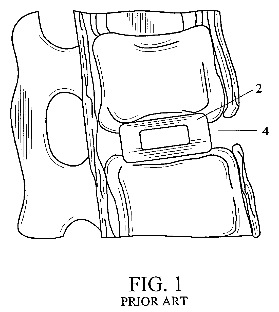
BACKGROUND OF THE INVENTION[0001]Single level spine fusion procedure typically entails removing the intervertebral disk (not shown) and inserting an interbody device 2 into the disk space 4, as shown in FIG. 1.[0002]Current spine fusion procedures rely heavily on the use of posterior fixation to achieve the stability and rigidity necessary to obtain successful clinical results. However, implantation of posterior instrumentation necessarily involves removing important musculoskeletal elements.[0003]Because of these concerns, anterior fixation systems have also been developed which require removal of much less musculoskeletal mass. However, because anterior fixation, especially in the abdominal or thoracic area, lies in close proximity to vital internal organs such as the aorta, these fixation systems must also possess a low profile.[0004]In general, conventional intervertebral connection systems can be characterized by ligament components which are either a) relatively rigid, or b) n...

Claims


Application Information

Patent Timeline
IPC IPC(8): A61B17/56A61F2/08A61B17/00A61L27/00A61B17/064A61B17/70A61F2/44
CPCA61B17/0642A61B17/70A61F2/0811A61B2017/00004A61B2017/0647A61B2017/0648A61F2/0805A61F2/4455A61F2002/087A61F2002/0888Y10S606/908
Inventor SERHAN, HASSAN ASLIVKA, MICHAEL AFAIR, CHRISTOPHER T
Owner DEPUY ACROMED INC
Why Eureka
Try Eureka