Fine contact hole forming method employing thermal flow process

a technology of thermal flow and contact hole, which is applied in the direction of instruments, gaseous heating fuel, stoves or ranges, etc., can solve the problems of irregularities in the flow amount, difficulty in controlling the desired contact hole size with respect to the heating temperature, so as to facilitate the adjustment of resist production and increase the manufacturing yield

Inactive Publication Date: 2008-03-18
SHIN ETSU CHEM IND CO LTD
View PDF20 Cites 10 Cited by
  • Summary
  • Abstract
  • Description
  • Claims
  • Application Information

AI Technical Summary

Benefits of technology

[0023]After formation of contact holes using a resist material, in a thermal flow step in which contact holes are contracted by baking it is possible to fix the contact hole size after thermal flow even with a change in resist material lot. Or it is possible to fix the contracted size, namely the flow amount, at the same bake temperature. Consequently, as well as facilitating adjustment of resist production, when manufacturing ultra LSI which is manufactured by ultrafine contact hole formation, there are advantages in facilitation of process management and increase in manufacturing yield.

Problems solved by technology

However, in the ultra fine contact hole forming method using this thermal flow technology, there is a problem that controlling the desired contact hole size with respect to the heating temperature is extremely difficult.
That is to say, every time when there is a lot change of the chemical amplification positive resist material, there is the problem of irregularities between lots of the resist material with fluctuations of the contact hole size after thermal flow, and fluctuations of the flow amounts despite heat treatment at the same temperature.
This problem gives rise to reductions in throughput because process management becomes extremely complex and time is required for the investigation.
In practice, even if the formulation is weighed out accurately with utmost care, when impurities are comprised in the base resin, the amount of base resin added differs, variations are observed as measuring errors and thermal flow is affected.
Similarly when impurities are contained in the acid generator (C), there are fluctuations between lots in the actual amount added, and it becomes problematic to accurately match to thermal flow between each lot.

Method used


Image

  • Fine contact hole forming method employing thermal flow process

Examples


examples

[0068]The present invention will be explained in more detail by showing examples. However, the invention is not limited to the examples.

[0069]For the positive chemical amplifying resist, a resist with the following composition is used.

(Resist Composition; Standard Composition)

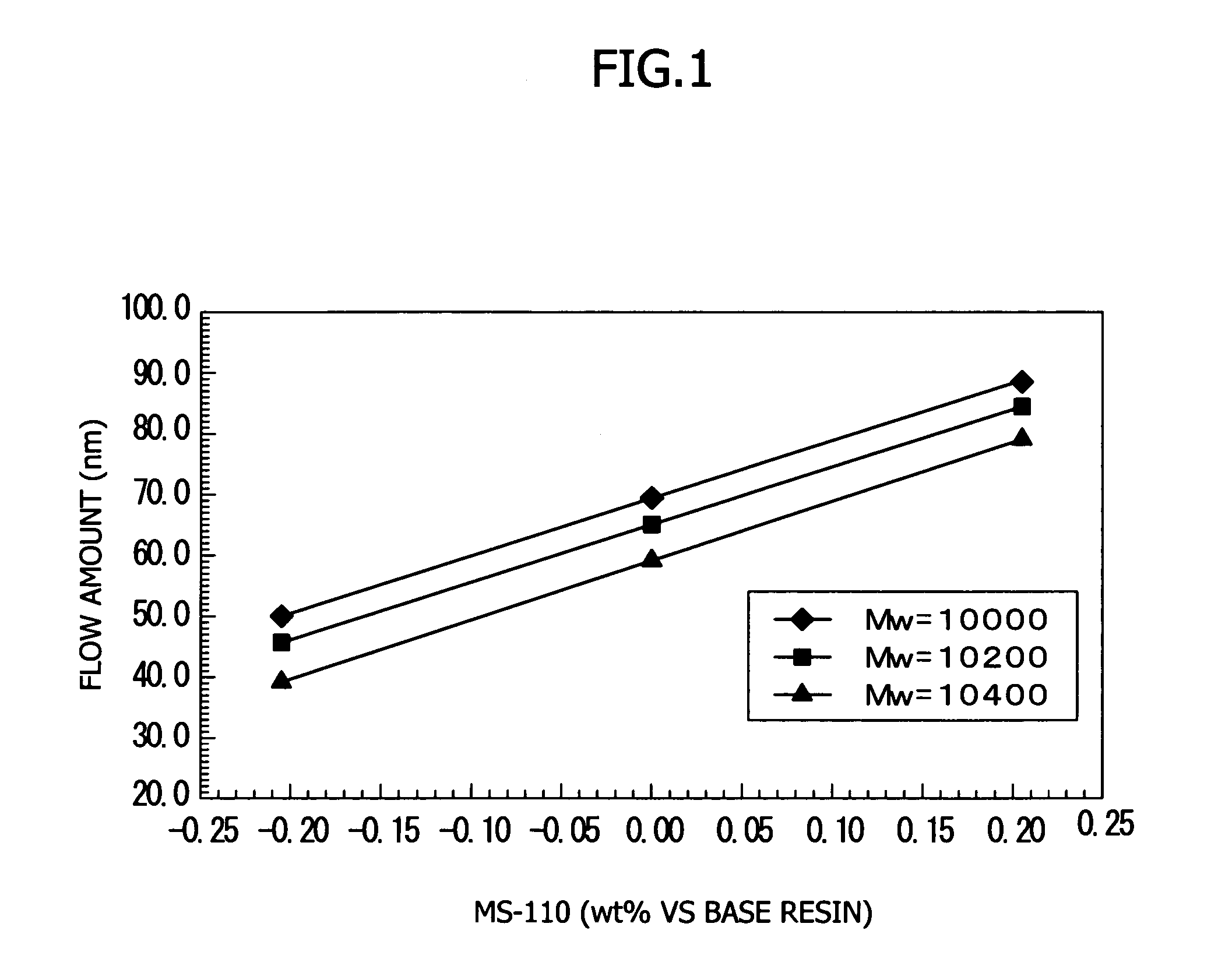
[0070]Polyhydroxystyrene having a weight-average molecular weight of 11,000, wherein 14 mol % of the hydroxyl groups thereof are protected by 1-ethoxyethyl groups and 13 mol % of the hydroxyl groups are protected by tert-butoxycarbonyl groups: 80 parts by weight.[0071]Bis(cyclohexylsulfonyl)diazomethane: 5 parts by weight.[0072]Triethanol amine: 0.125 parts by weight[0073]Surfactant: FC-430S (Made by Sumitomo 3M Corporation): 0.01 parts by weight[0074]Propyleneglycol monomethyl ether acetate: 450 parts by weight[0075]Emulgen MS-110 (Made by Kao Corporation): 1.0 wt % with respect to the base resin.

[0076]After the obtained resist material solution is filtered through a 0.2 μm Teflon (registered trade-mark) filte...


PUM

PropertyMeasurementUnit
boiling pointaaaaaaaaaa
diameteraaaaaaaaaa
sizesaaaaaaaaaa

Abstract

Provided is a contact hole forming method, wherein in a thermal flow step the contact hole size can be fixed after thermal flow even if the resist material lot changes, or, wherein at the same bake temperature the contracted size, namely the flow amount, can be fixed. More specifically, provided is a contact hole forming method comprising a step of coating a resist material onto a substrate, a step of heating the coated resist material, a step of exposing the heated resist material to light through a photo mask adapted for a contact hole pattern, a step of heating the exposed resist material, a step of forming the contact hole pattern subsequently by developing with a developing fluid and a step of thermal flow treatment for heating the obtained contact hole pattern, wherein the resist material comprises an organic compound which does not react with the other components within the resist material and does not change a resolution property, and wherein when the resist material lot is changed, an amount of the organic compound to be added is changed so as to keep the contact hole pattern identical before and after the lot change.

Description

CROSS-REFERENCE TO RELATED APPLICATIONS[0001]The present application claims priority to Japanese Patent Application No. 2003-128577, filed May 7, 2003, the disclosure of which is incorporated herein by reference in its entirety.BACKGROUND OF THE INVENTION[0002]1. Field of the Invention[0003]The present invention relates to the step of further contracting a contact hole size called thermal flow which is heat treatment for a contact hole pattern in the formation of contact holes. More specifically, the present invention relates to ultra fine contact hole forming methods for adjustably varying the amount of a stable organic compound which does not react with the various components of the resist material and which does not alter a resolution property. It can circumvent the problems of post thermal flow contact hole size fluctuations and fluctuations in contraction size and flow amount which occur despite heating at identical temperatures when the resist material lots change. Thus, easy ...

Claims


Application Information

Patent Timeline
Patent Type & Authority Patents(United States)
IPC IPC(8): G03F7/00G03F7/004G03F7/039G03F7/40H01L21/027H01L21/302H01L21/44H01L21/461H01L21/768
CPCG03F7/40H01L21/76802F17D3/01F23N5/247F24C3/12
Inventor TAKEMURA, KATSUYASEKI, AKIHIROFUKUDA, EIJI
Owner SHIN ETSU CHEM IND CO LTD
Why Eureka
Try Eureka