Light-pipe integrator for uniform irradiance and intensity

a light-pipe integrator and uniform irradiance technology, applied in the field of optical systems, can solve the problems of insufficient brightness conservation, similar or worse irradiance and intensity non-uniformity, and the distribution of led source light output using conventional optical means, so as to eliminate the need for complex design and expensive, optimize light collection, and high fill-factor of the light source aperture

Inactive Publication Date: 2008-04-01
EDMUND OPTICS
View PDF3 Cites 13 Cited by
  • Summary
  • Abstract
  • Description
  • Claims
  • Application Information

AI Technical Summary

Benefits of technology

[0014]According to one aspect of the invention, the focusing optical element and the second ILP are used to homogenize the intensity distribution of the light received from the first ILP. In particular, the focusing element is used to swap the irradiance and intensity distributions, converting the non-uniform intensity distribution in the output of the first ILP to a non-uniform irradiance distribution in the input of the second ILP, and the uniform irradiance distribution in the output of the first ILP to a uniform intensity distribution in the input of the second ILP. This allows the subsequent ILP stage to complete the re-distribution of light by transforming the non-uniform irradiance in its input to a uniform irradiance in its output, while again leaving the intensity distribution with respect to the optical axis substantially unaltered. As those experienced in optics will readily understand, such sequence of transformations produces a homogeneous light output independent of spectral or spatial characteristics of the source, both in intensity and irradiance. The focusing optical element may be refractive (such as a simple lens) or diffractive, but it is preferably reflective (a mirror) to avoid introducing chromatic aberrations into the system.
[0015]According to another aspect of the invention, a light integrator is added to the LED-based optical system to eliminate the need for a complex design and expensive construction of the LED-array source and the primary light-collecting optics. This advantage follows from the fact that the function of spatial blending of light is fully executed by the light integrator and, therefore, it is not part of the function of the optics of the mixed-color light source. As a result, the only purpose of the die of light emitters and the collecting optics remains to provide a high fill-factor of the light source aperture; namely, to optimize light collection for the preservation of brightness. This allows for a significantly simplified design of the LED arrays and the collecting optics containing these arrays.

Problems solved by technology

Still, the distribution of the light output from LED sources using conventional optical means is known to lack homogeneity of both irradiance and intensity.
Sources other than LEDs may pose similar or worse irradiance and intensity non-uniformity challenges, as well as possibly polarization conditions that will make the source perform differently than traditional sources if not redistributed by the collection system.
Although preserving brightness is a necessary feature of a collection system, high performance with respect to brightness conservation is not enough if the resulting output contains significant elements of the various types of possible non-uniformities found at the input.
Although the specific impact of non-uniformity in the output varies, the effect is generally undesirable and performance limiting for most visual- and sensor-based applications.
While non-uniformities from a narrow band source would be objectionable in many applications, the problem of non-uniformity of irradiance and intensity of light output is particularly pronounced when arrays of spectrally different LEDs (such as the RGB arrays of FIG. 1) are used for broadband illumination of objects.
The problem is manifested in the fact that any mismatch in the irradiance or intensity profile in the light output produced by each individual LED produces a non-uniform color distribution in the viewing plane (or in the detector plane).
The additional degree of non-uniformity of such a mixed-color LED array (versus a single color array with only spatial non-uniformities) within a single light-collecting system only aggravates the problem of non-uniformity in the output.
Although the degree and impact of such color non-uniformity depend on several factors (such as spectral bands, number and arrangement of LEDs used, the particular optical scheme, and the application), this effect is nearly universally undesirable.
For instance, the image of a multi-colored object illuminated by such an optical source will not accurately reproduce the coloration of the object and, therefore, will convey erroneous optical information.
Even in monochromatic imaging applications (such as in machine vision) the spatial color non-uniformity of the illumination source will result in perceiving a uniformly colored object as having gray-level variations due to the variable spectral response of the optical receiver.
Thus, while ILPs may be used to provide a uniform irradiance distribution of light, any non-uniformity of intensity remains substantially non-uniform and a problem that is yet unsolved.
This deficiency of conventional ILP-based illumination systems makes mixed-color LED arrays, packaged within a single collecting optic, unsuitable for all but very low-end illumination applications.
As the light propagates away from the output plane, significant color and general irradiance non-uniformities will likely be present along the path due to the unresolved differences in the angular distribution.
Therefore, there exists an unresolved problem in the angular uniformity of the distribution of the light produced by both narrow band and mixed-color sources (such as single or multi-color LED arrays).

Method used


Image

  • Light-pipe integrator for uniform irradiance and intensity
  • Light-pipe integrator for uniform irradiance and intensity
  • Light-pipe integrator for uniform irradiance and intensity

Examples


Embodiment Construction

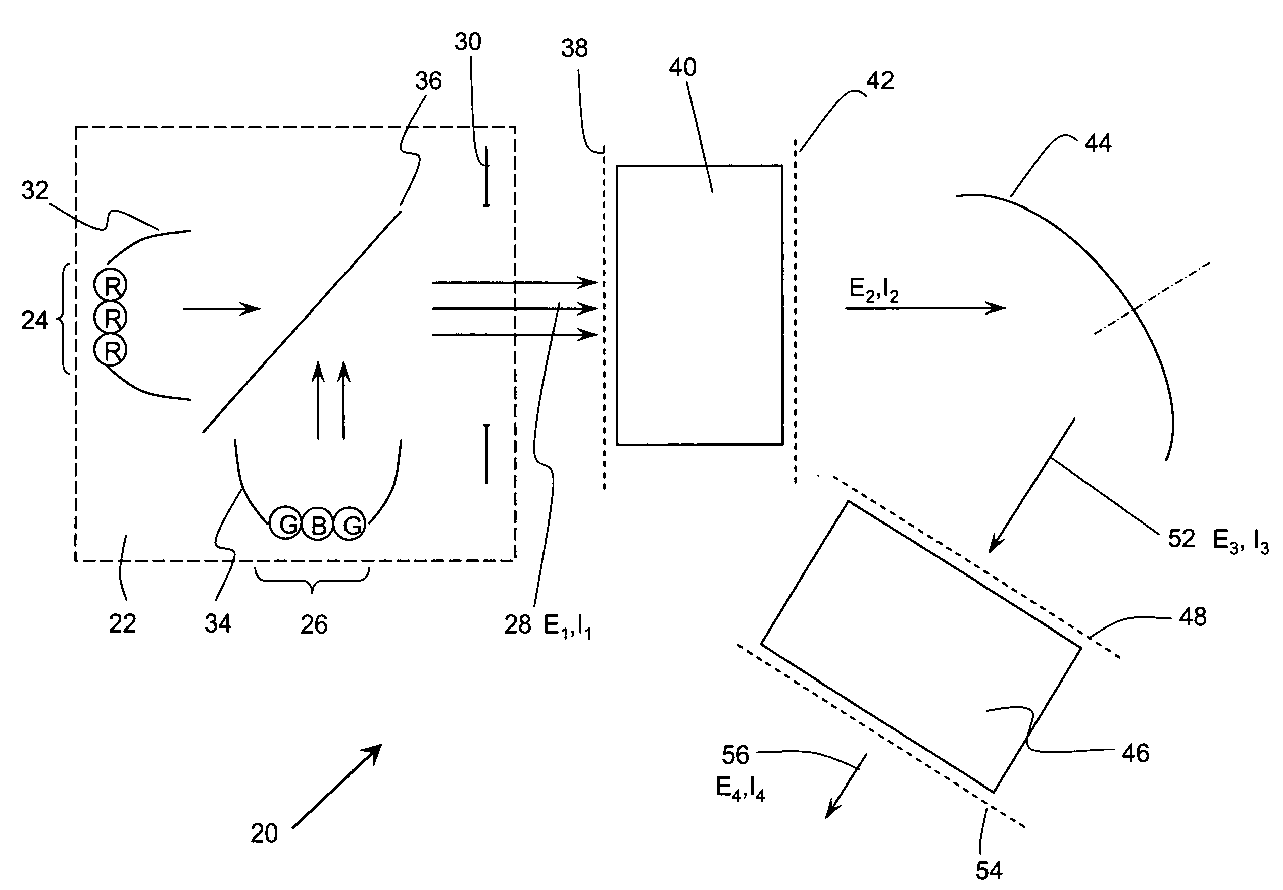
[0029]As mentioned above, the functional performance of ILPs is limited by the fact that the light pipe homogenizes only the irradiance distribution of the light propagating through it, leaving the intensity distribution substantially non-homogeneous. Specifically, the ILP equalizes (at all frequencies) the surface density of the light in any part of the ILP's cross-section, but it does not even out the angular density of the light. As a result, the amount of light energy propagating in a unit solid angle in a certain direction at the output of the ILP generally differs from that propagating in another direction. FIG. 4 provides an illustration to this limitation of conventional ILPs. Therefore, this invention is based on the novel idea of “swapping” the angular space and transverse plane distributions of the light at the output of a first ILP and passing such light through a second ILP to homogenize not only the irradiance, but also the intensity distribution.

[0030]As used herein, ...


PUM


Abstract

Two integrating light pipes are optically coupled to a focusing element to produce light with uniform irradiance and intensity profiles. The first ILP stage is used to receive spatially non-uniform light from a single or multi-color source and produce a uniform irradiance distribution while leaving the intensity distribution substantially unaltered. The focusing optical element swaps the irradiance and intensity distributions received from the output of the first ILP and feeds it to a second ILP stage which, in turn, completes the spatial homogenization of the light by transforming the non-uniform irradiance received from the focusing element into an output of uniform irradiance. As a result of this sequence of transformations, a homogeneous multi-color light output, both in intensity and irradiance, is produced.

Description

RELATED APPLICATIONS[0001]This application is based on U.S. Provisional Application Ser. No. 60 / 685,728, filed on May 27, 2005.BACKGROUND OF THE INVENTION[0002]1. Field of the Invention[0003]This invention relates in general to optical systems that spatially homogenize light produced by non-homogenous optical sources. In particular, it relates to methods and systems that utilize spatially homogenizing light pipes in combination with optics with positive optical power to produce a light output that is uniform both in intensity and irradiance from a single source or an array of light-emitting diodes. The substantial spatial and possibly spectral non-uniformity in the input aperture of the optical system introduced by this type of source generally translates into non-uniformity in the output of traditional light collection systems.[0004]2. Description of the Related Art[0005]Light-emitting diodes (LEDs) have already gained popularity in various applications as versatile optical sources...

Claims


Application Information

Patent Timeline
Patent Type & Authority Patents(United States)
IPC IPC(8): G02B27/10F21V7/00G02B17/00G02B7/00G05D25/00F21K99/00H01L33/00H01L33/58H01L33/60
CPCG02B27/0994F21K9/00F21K9/62
Inventor CUMMINGS, CHRISTOPHERSADOULET, SAMUEL P.
Owner EDMUND OPTICS
Why Eureka
Try Eureka