Method for producing alignment mark

Active Publication Date: 2008-04-08
HITACHI METALS LTD
View PDF23 Cites 4 Cited by
  • Summary
  • Abstract
  • Description
  • Claims
  • Application Information

AI Technical Summary

Benefits of technology

[0021]In order to overcome the problems described above, preferred embodiments of the present invention provide a method for producing an alignment mark that can be easily removed from the substrate surface without leaving any trace of the alignment mark, after the alignment mark has been used for alignment in the lithography process.

Problems solved by technology

According to this method, however, a portion of the substrate surface is melted and scattered by the laser irradiation.
As a result, there is a problem in that the engraved portion becomes a source of dust.
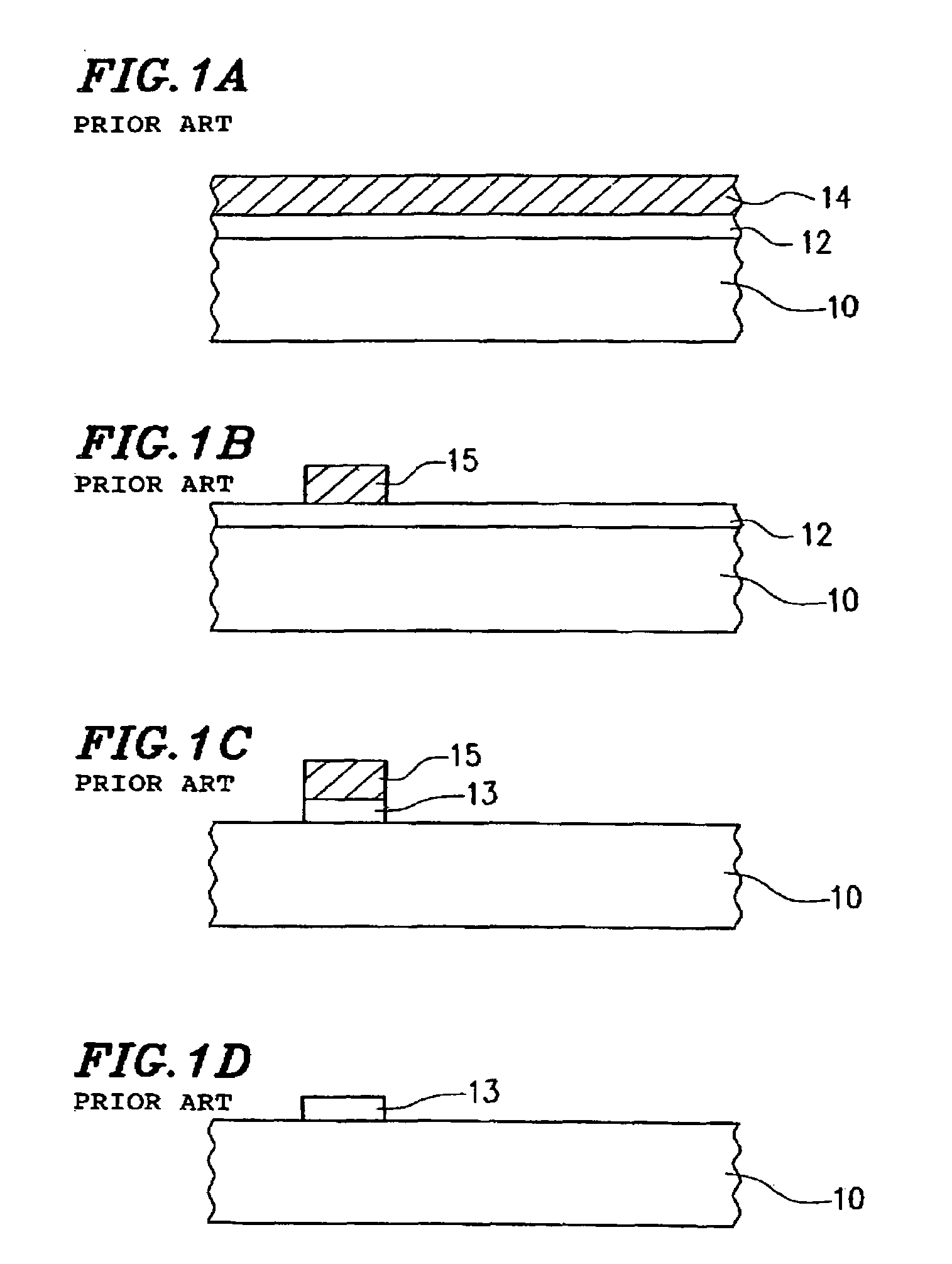
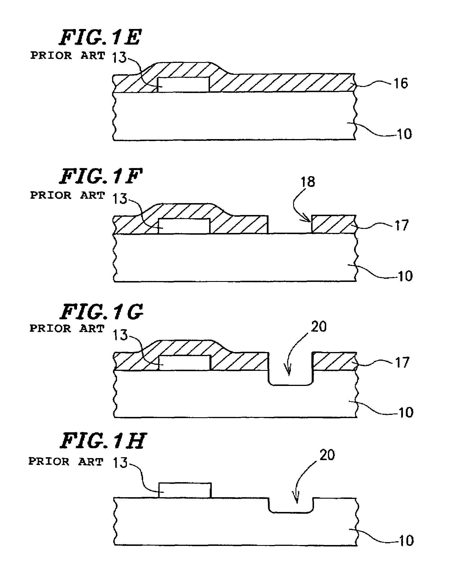
If there is an unnecessary convex portion such as the alignment mark 13 in a substrate provided with identification information as described above, many problems occur including the flatness of the multi-layer structure to be formed on the substrate 10 being degraded.
In the case where identification information is engraved on the back side of the substrate 10, if the above described alignment mark 13 remains on the back side of the substrate 10, there is also a concern that some problems will occur when the substrate is transported, and the substrate is fixed to the holders (the members for holding a substrate) in a variety of instruments.
However, it is difficult to carry out the dry etching over a wide surface area of a substrate with a uniform rate, and accordingly, it is necessary to adopt the etching conditions that allow overetching to occur in order to prevent insufficient etching from occurring.
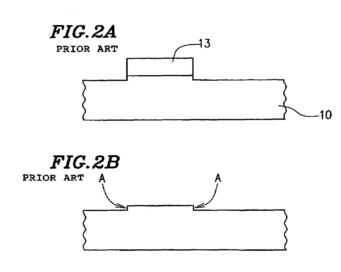
Such steps A persist after the removal of the alignment mark 13, and thus possibly cause the degradation of the read accuracy when identification information is optically read.

Method used


Image

  • Method for producing alignment mark
  • Method for producing alignment mark
  • Method for producing alignment mark

Examples


embodiment 1

Preferred Embodiment 1

[0049]Description is made below of a first preferred embodiment of a method for producing an alignment mark according to the present invention with reference to the drawings. In the present preferred embodiment, identification information is engraved on a Al2O3—TiC based ceramic wafer preferably including two types of composite materials, namely, Al2O3 and TiC.

[0050]In the first place, as FIG. 3A shows, after a first photoresist layer 32 having a thickness of the order of about 0.1 μtm to about 10 μm has been formed on the ceramic substrate 30, a prebake process is performed for the purpose of evaporating the solvent in the resist material. The temperature and duration of the prebake process are appropriately set according to the type of the photoresist. Then, as FIG. 3B shows, the photoresist layer 32 is exposed and developed, and thus an alignment mark 33 is formed from the first photoresist layer 32.

[0051]In the present preferred embodiment, after the substr...

embodiment 2

Preferred Embodiment 2

[0060]Description is made below of a second preferred embodiment of a method for producing an alignment mark according to the present invention with reference to FIG. 4.

[0061]In the first place, according to the method similar to that used in the first preferred embodiment, an alignment mark 33 having a thickness of about 0.1 μm to about 10 μm is formed on a substrate 30 (FIG. 4A). Specifically, after the substrate has been coated with a negative photoresist by a spin coat method or other suitable process, light is irradiated to the prescribed portion on the negative photoresist layer through a photomask defining the pattern for the alignment mark. The light irradiated portion (exposed portion) on the photoresist layer becomes insoluble in a developer owing to the photo-crosslinking reaction. By dissolving the unexposed portion in the developer in the development process, the alignment mark 33 can be formed which is made from the exposed portion of the photores...


PUM


Abstract

A method for producing an alignment mark is performed such that the alignment mark can be removed from the surface of a substrate without leaving any trace thereof after the alignment mark has been used for alignment. After a first photoresist layer has been formed on a substrate, the first photoresist layer is subjected to patterning, and the alignment mark is thereby formed from the first photoresist layer. In the next step, after a second photoresist layer has been formed so as to cover the alignment mark, the second photoresist layer is subjected to patterning on the basis of the alignment mark. After the surface of the substrate has been subjected to etching by use of a resist mask thus formed, the resist mask and the alignment mark are removed, and the region where the alignment mark has been located is made flat.

Description

BACKGROUND OF THE INVENTION[0001]1. Field of the Invention[0002]The present invention relates to a method for producing an alignment mark, a method for producing a resist mask, a method for transferring a pattern, a method for producing a substrate provided with identification marks, and a method for manufacturing a ceramic substrate for use in a magnetic head.[0003]2. Description of the Related Art[0004]A ceramic substrate for use in a magnetic head is laminated with a magnetic thin layer and the like, and is eventually divided into a plurality of chips. Each of the chips is incorporated into a magnetic head. For the purpose of identifying what substrates the individual chips originate from, it is convenient to record identification information in a prescribed portion on a substrate. For the purpose of identifying what portion of a substrate a chip originates from, it is convenient to allocate unique information to the individual portions (corresponding to the individual chips) of ...

Claims


Application Information

Patent Timeline
IPC IPC(8): G03F9/00G11B5/31H01L21/02H01L21/027H05K1/02H05K1/03H05K3/00
CPCG03F9/7076G03F9/708G03F9/7084H05K1/0269H05K1/0306H05K3/002H05K2201/09036H05K2201/09918H05K2203/0574
Inventor HIROOKA, TAISUKE
Owner HITACHI METALS LTD
Why Eureka
Try Eureka