
Frequency control apparatus for controlling the operation frequency of an object

a technology of operation frequency and control apparatus, which is applied in the direction of generating/distributing signals, instruments, sustainable buildings, etc., can solve the problems of insufficient flexibility, inability to fix the operation state or load situation, and insufficient degree of freedom in design, so as to improve performance and save power

Inactive Publication Date: 2008-04-08
SONY CORP
View PDF20 Cites 19 Cited by
  • Summary
  • Abstract
  • Description
  • Claims
  • Application Information

AI Technical Summary

Benefits of technology

[0007]It is an object of the present invention to provide a frequency control apparatus and an information processing apparatus wherein it is possible, in control of an operation frequency of a control object performed in response to a result of observation of an operation state of the control object, to Emit the operation frequency or designate an allowable value or the like to achieve improvement in performance and power-saving.
[0010]With the frequency control apparatus and the information processing apparatus, if the frequency determined in response to the operation state of the control object is within an allowable range or has an allowable value, the control is performed with the frequency. However, if the frequency is outside the allowable range or does not have the allowable value, the frequency is limited to the allowable range or allowable value Consequently, the control can be performed appropriately and prevent occurrence of an unintended situation.
[0011]Further, since a countermeasure is taken for limiting the operation frequency of the control object, it is assured to perform appropriate frequency control in accordance with a load characteristic or the like, and therefore, augmentation in performance and power-saving can be anticipated Besides, an extensive design change in ah or the like is no required.
[0012]Also it is possible to limit the operation frequency so that it may not come out of a prescribed or designated frequency range or invalidate an unexpected frequency value.
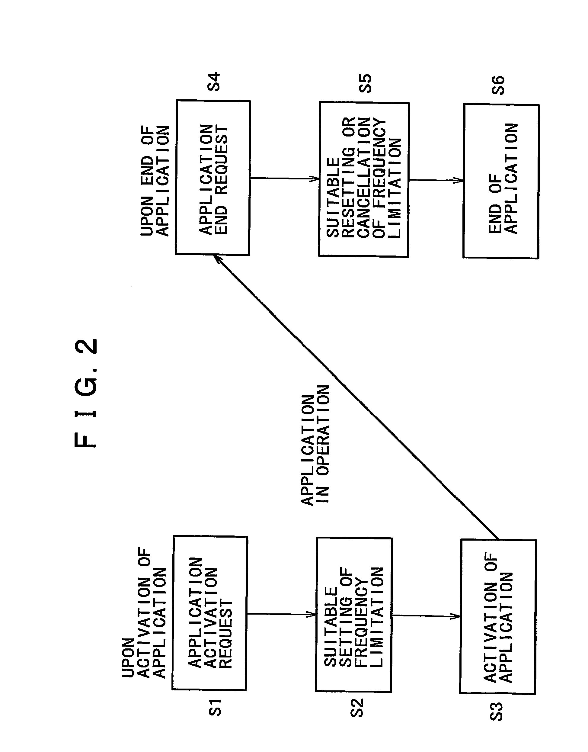
[0015]Further, since an optimum frequency value or frequency range can be designated, deterioration of a performance, increase of power consumption and so forth can be prevented. Further, it is possible to prevent setting of operation frequency limitation by the program from having a bad influence on a process after execution of the program comes to an end.

Problems solved by technology

However, the operation state or the load situation is not fixed with an information processing apparatus such as a computer.
The method of the Patent Document 1, however, has a problem in that, where a system frequently repeats a transition between a standby state and an operation state, it is necessary to perform a changeover process of the clock frequency every time.
The method of the Patent Document 2 has another problem in that a circuit for supervising the load situation of a bus is required and also in that-it is not sufficiently high in flexibility in that the load situation of the bus and the load situation of the system do not always coincide with each other.
The architecture described above, however, has a problem in the degree of freedom in design in regard to control for determining an operation frequency appropriate to an operation state of a system.
For example, where an architecture which includes an observation circuit or a like circuit for supervising an operation state of a target circuit, that is, an object of frequency control includes a hardware configuration for calculating an optimum clock frequency through fixed circuit calculation from a result of the observation of the clock frequency, it is difficult to control the frequency paying sufficient attention to the accuracy, a characteristic of a load itself and so forth.
Therefore, it is almost impossible to implement a configuration for determining an optimum frequency for all of the task types.
Or, since a configuration or process which is much complicated in mounting of hardware is inevitably required, the architecture described above has a problem in terms of the cost and the design.

Method used


Image

  • Frequency control apparatus for controlling the operation frequency of an object
  • Frequency control apparatus for controlling the operation frequency of an object
  • Frequency control apparatus for controlling the operation frequency of an object

Examples


Embodiment Construction

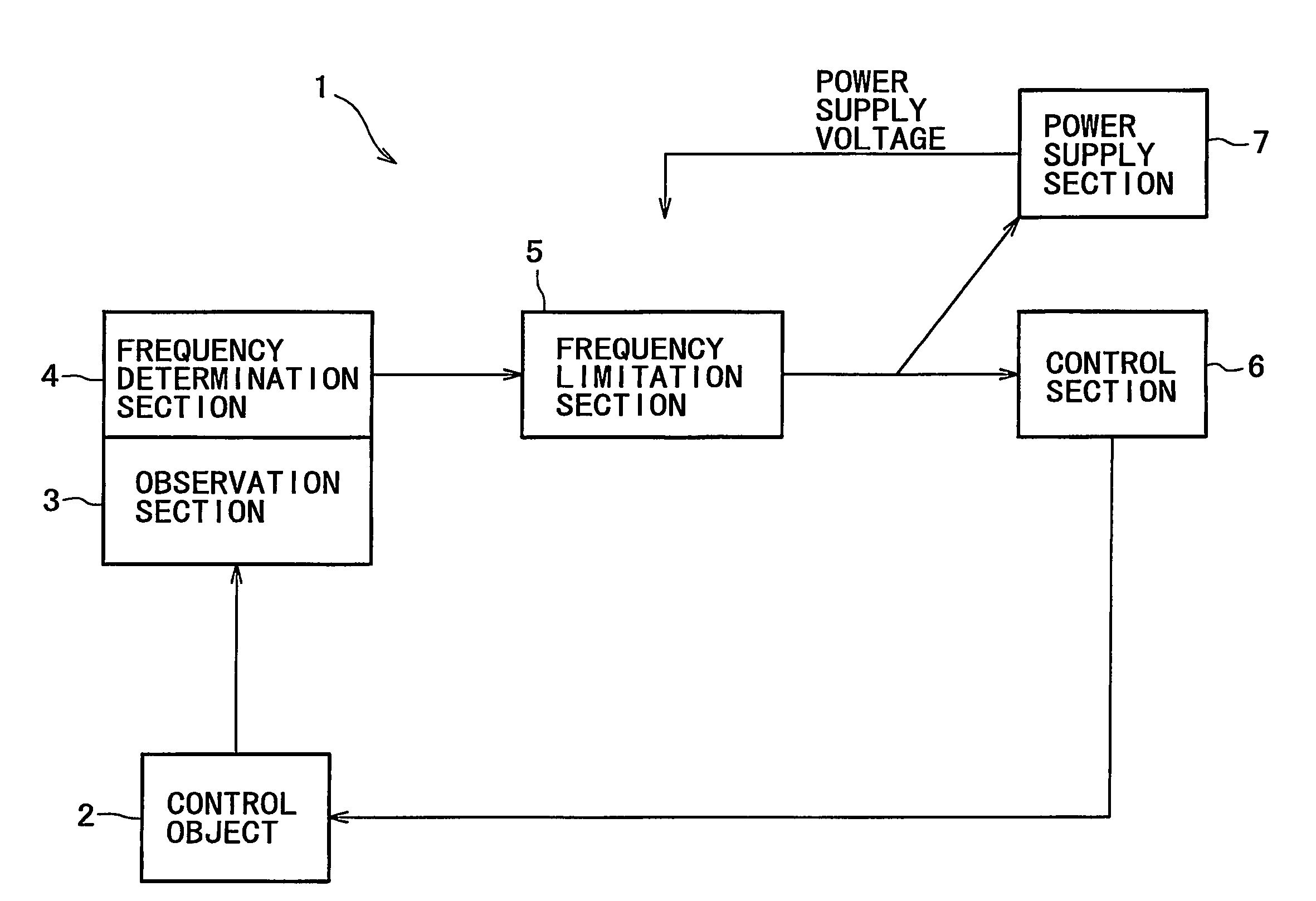
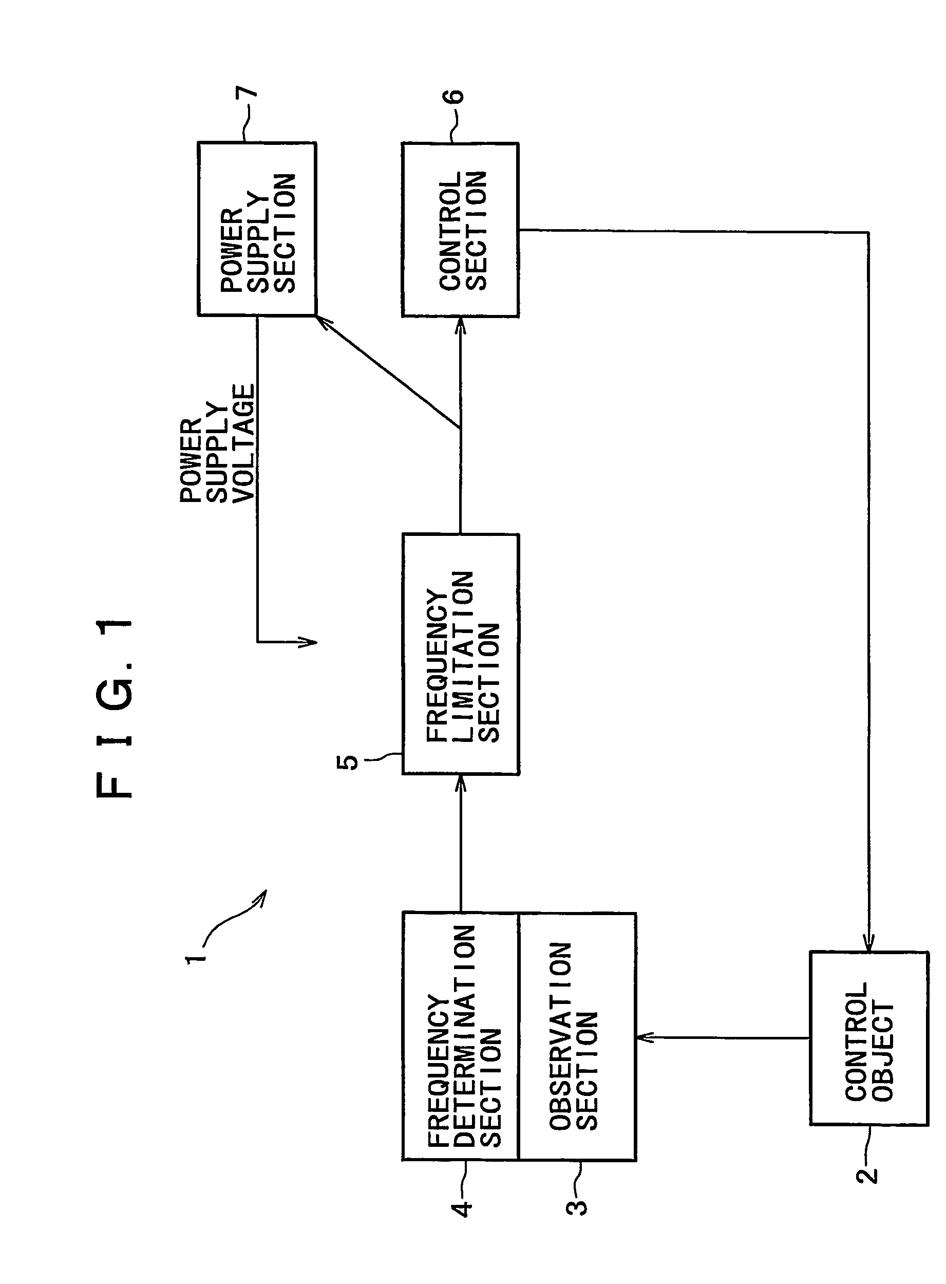
[0028]FIG. 1 conceptive illustrates an example of a basic configuration of a frequency control apparatus of an information processing apparatus according to the present invention. Referring to FIG. 1, it is presupposed that a frequency control apparatus 1 can control the operation frequency of a control object 2 of the information processing apparatus. For example, a central processing unit (CPU), a coprocessor and an image pickup device can be listed as a device for arithmetic operation processing which operates based on a frequency selectively set among a plurality of clock frequencies and may be used as the control object

[0029]The frequency control apparatus 1 includes an observation section 3 for observing an operation condition of the control object 2 and controls the operation frequency of the control object 2.

[0030]A frequency determination section 4 is provided to determine the operation frequency of the control object 2 in response to an operation condition of the control o...


PUM


Abstract

A frequency control apparatus and an information processing apparatus includes an observation section for observing an operation state of a control object which operates with a variably controlled frequency, a frequency determination section for determining a clock frequency in response to the operation state, and a frequency limitation section for limiting a range or a value of the clock frequency determined by the frequency determination section. If the frequency determined in response to the operation state of the control object is within an allowable range, the control is performed with the frequency, but if the frequency is outside the allowable range, the frequency is limited to the range.

Description

TECHNICAL FIELD[0001]This invention relates to a technique for observing an operation state of a control object to appropriately control the operation frequency of the control objectBACKGROUND ART[0002]The power consumption of an electronic circuit system depends upon the power supply voltage and the clock frequency for operating the system, that is, increases in proportion to the square of the power supply voltage and to the frequency of the clock. However, the operation state or the load situation is not fixed with an information processing apparatus such as a computer. An architecture of a system is known wherein the system state changes such that, for example, when the system has a task to process, it operates, but when it has no other task to process after the process of the task comes to an end, the system enters a standby state.[0003]Several methods are known wherein an operation state of a system is observed and a clock or the like is controlled to reduce wasteful power cons...

Claims


Application Information

Patent Timeline
Patent Type & Authority Patents(United States)
IPC IPC(8): G06F1/04G06F1/32H03L7/06H03L7/07H03L7/099H03L7/16
CPCG06F1/3203G06F1/324H03L7/06H03L7/0991H03L7/16Y02B60/1217H03L7/07Y02D10/00G06F1/32
Inventor SHIMOYAMA, TAKESHIMEGURO, TETSUMASATERANISHI, TSUTOMUNAKANO, YASUOKAWAHARA, HIROKAZU
Owner SONY CORP
Learn More