Fiber optic collimator system, fiber optic collimator array, and manufacturing method of the fiber optic collimator system and fiber optic collimator array system

a technology of fiber optic collimator and array system, which is applied in the direction of manufacturing tools, instruments, optical elements, etc., can solve the problems of complex core alignment processing in various axial directions, and achieve the effect of efficient production, efficient fabricated, and remarkable facilitation

Active Publication Date: 2008-04-15
TOYO SEIKAN GRP HLDG LTD
View PDF12 Cites 31 Cited by
  • Summary
  • Abstract
  • Description
  • Claims
  • Application Information

AI Technical Summary

Benefits of technology

[0037]According to the fiber optic collimator system and the fiber optic collimator array system of the present invention, since the GRIN lens and the optical fiber being already spliced are employed, an axial alignment of the lens and the optical fiber is not required in the assembling process, and accordingly the systems can be efficiently fabricated. Further, since the GRIN lens and the optical fiber are fused and spliced, the axes of the GRIN lens and the optical fiber automatically coincide due to a self alignment effect caused by surface tension in fusing. Thus, the production is remarkably facilitated and mass production is also possible. Moreover, since the adhesive is not used, even if a highly intensive light is input, the problem of deterioration in the optical characteristics caused by alteration of the adhesive due to the elevated temperature does not occur.
[0038]According to the fiber optic collimator system of the present invention, trends of the horizontal position displacements and the inclination angles are examined for a plurality of trial products. Based on this result, the permitted amount of horizontal position displacement, and the permitted inclination angle, can be obtained to attain a targeted yield and a targeted coupling loss. A minimum value of the NA required for the GRIN lens can be obtained from the permitted amount of horizontal position displacement and the permitted inclination angle. Thus, the targeted yield and the targeted coupling loss can be attained efficiently at low costs, without using a GRIN lens with a larger NA than necessary.
[0039]According to the fiber optic collimator array system, as well as the above-mentioned fiber optic collimator system, trends of the horizontal position displacements and the inclination angles are examined for a plurality of trial products. Based on this result, the permitted amount of horizontal position displacement, and the permitted inclination angle can be obtained to attain a targeted yield and a targeted coupling loss. A minimum value of the NA required for the GRIN lens can be obtained from the permitted amount of horizontal position displacement and the permitted inclination angle. Thus, the targeted yield and the targeted coupling loss can be attained efficiently at low costs without using a GRIN lens with a larger NA than necessary.

Problems solved by technology

As described above, conventionally, subtle and complicated core alignment processing has been required in various axial directions.

Method used


Image

  • Fiber optic collimator system, fiber optic collimator array, and manufacturing method of the fiber optic collimator system and fiber optic collimator array system
  • Fiber optic collimator system, fiber optic collimator array, and manufacturing method of the fiber optic collimator system and fiber optic collimator array system
  • Fiber optic collimator system, fiber optic collimator array, and manufacturing method of the fiber optic collimator system and fiber optic collimator array system

Examples


embodiment 1

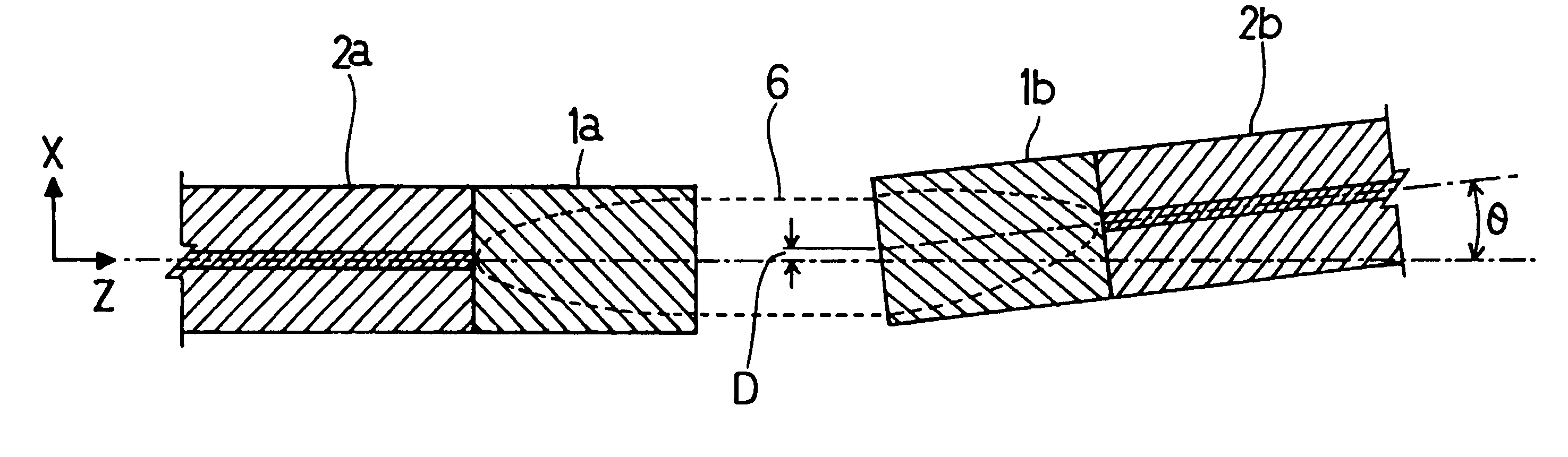
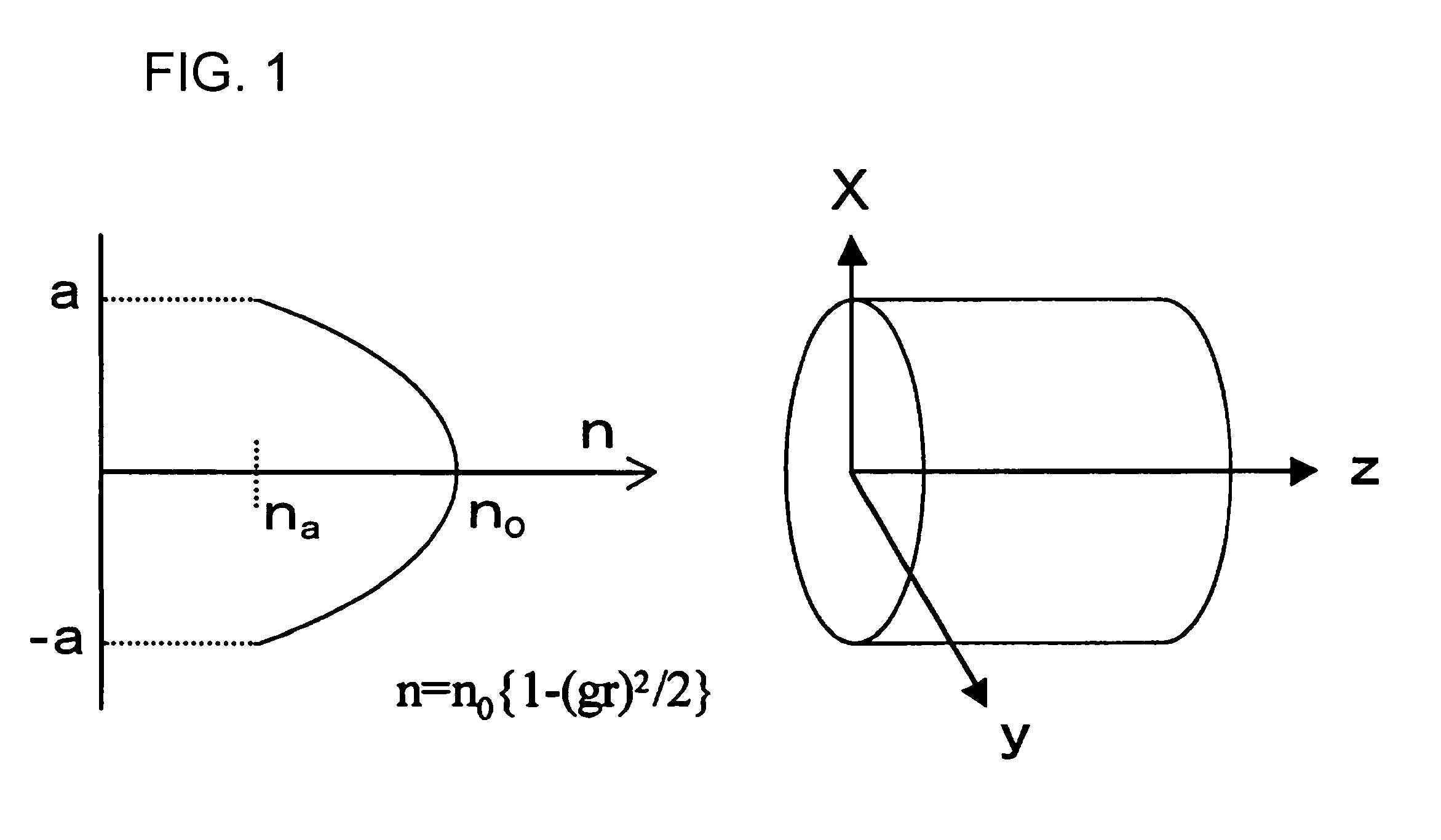
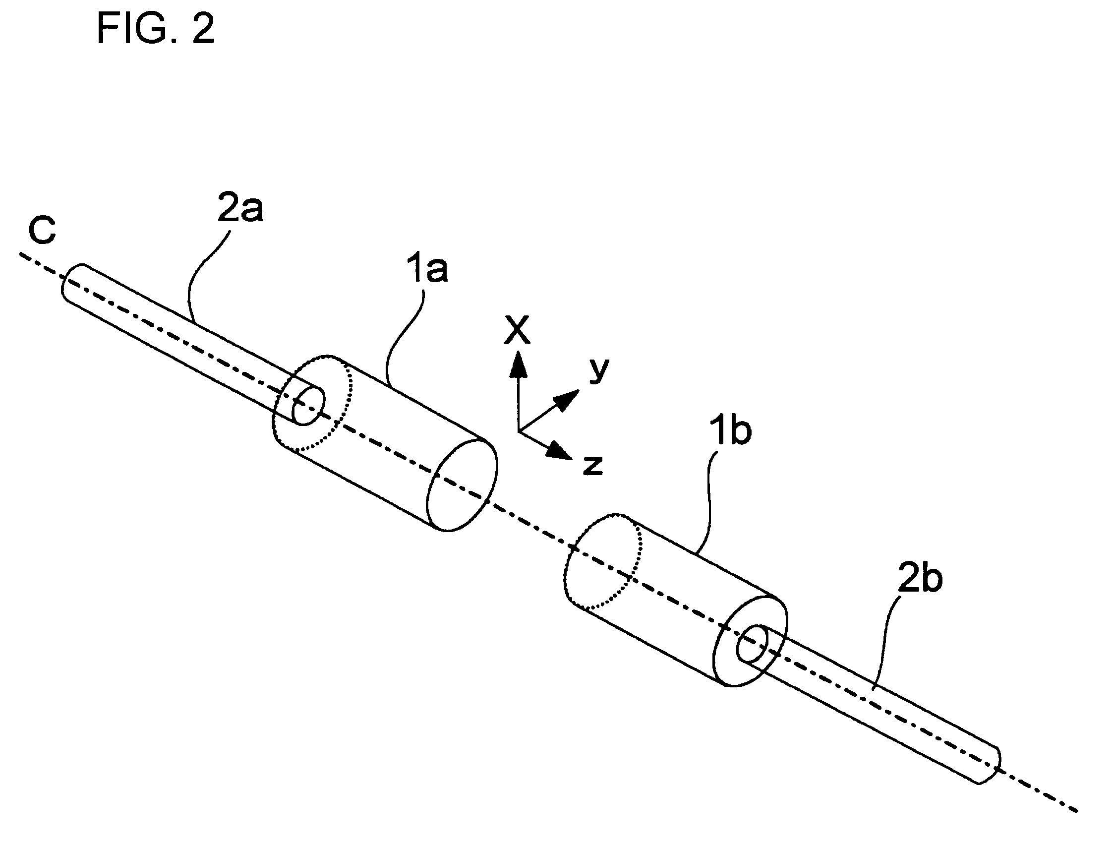
[0083]FIG. 7 shows the fiber optic collimator system of the first embodiment. The optic fibers 2a and 2b with GRIN lenses 1a and 1b are inserted from both sides of the tubular collimator holder 9, and then adhered and fixed to attach the optical element 10 (in this case, the optical isolator) to the center. Approximately 230 sets of the collimator systems are carefully fabricated. The horizontal displacements (position displacement D) with regard to the X and Y directions and the inclination angles (angle displacement) θx and θy of the opposed GRIN lenses are measured. FIG. 8 shows the accumulative counts of the horizontal displacements in the X and Y directions (position displacements). FIG. 9 shows the accumulative counts of the inclination displacements with regard to the X and Y directions (angle displacements) θx and θy. FIGS. 8 and 9 show that the horizontal displacements are distributed with the peak of −0.3 μM and approximately ±1 μm width, and the inclination angle displace...

embodiment 2

[0088]FIGS. 10 and 11 relate to the optical fiber collimator arrays of the second embodiment. The end portions of the GRIN lens attaching to the optical fiber are regularly arranged in eight (8) rows along periodic V-grooves 13 formed by chemical etching on the SiO2 board 12. Further, these are regularly laminated in eight (8) steps, fixed to a frame 14, and thereby 8×8 GRIN lens collimator arrays were produced. Using this collimator array, a set of optical fiber collimator arrays, into which two MEMS-type optical switch arrays 3 with 2 degrees of freedom shown in FIG. 3 are inserted, were carefully fabricated. The horizontal displacements in the X and Y directions (position displacement D) and the inclination angles (angle displacement) θx and θy were measured for each pair of the opposing GRIN lens. FIG. 12 shows the accumulative counts of the horizontal displacements in the X and Y directions (position displacement). FIG. 13 shows the accumulative counts of the inclination angles...


PUM

PropertyMeasurementUnit
degrees of freedomaaaaaaaaaa
reflection anglesaaaaaaaaaa
inner diametersaaaaaaaaaa

Abstract

A fiber optic collimator system, a fiber optic collimator array, and a fiber optic collimator array system, which can reduce difficulty in an alignment process, minimize a coupling loss, and prevent the optical characteristics from deteriorating. An optical fiber is fused to one end of a GRIN lens made of quartz glass containing one or more selected from Sb2O3, Ta2O5, TiO2 and ZrO2 as a refractive index regulating substance, to form an optical fiber with a GRIN lens. Since an adhesive is not used, the core alignment of the GRIN lens and the optical fiber can be facilitated by a self alignment effect without deteriorating the optical characteristics. Moreover, the coupling loss is remarkably reduced by appropriately setting a refractive index distribution constant g of the GRIN lens. By fabricating the fiber optic collimator system, the fiber optic collimator array, the fiber optic collimator array system using the optical fiber with a GRIN lens can reduce the difficulty in the core alignment process, minimize the coupling loss, and prevent the optical characteristics from deteriorating.

Description

BACKGROUND OF THE INVENTION[0001]1. Technical Field[0002]The present invention relates to a fiber optic collimator system that disposes optical fibers with GRIN lenses being opposingly arranged and holding arbitrary optical elements, a fiber optic collimator array comprising a plurality of optical fibers with GRIN lenses being positioned in parallel, a method of manufacturing the fiber optic collimator system, and a method of manufacturing the fiber optic collimator array system that disposes the fiber optic collimator arrays in an opposed arrangement.[0003]2. Description of the Related Art[0004]In conventional optical information transmission, an outgoing light which is a light emerged from one optical fiber, is converted to a parallel light by a collimator lens. The parallel light after propagation is collected by another collimator lens, and is input to another optical fiber. Such an optical system is called a “collimator system” whereby a diverse optical module can be constructe...

Claims


Application Information

Patent Timeline
Patent Type & Authority Patents(United States)
IPC IPC(8): C03B37/00G02B6/38
CPCG02B6/32G02B6/2551G02B6/2746G02B6/2937G02B6/3512G02B6/3556G02B6/3652G02B6/3676G02B23/10
Inventor MATSUMURA, HIROYOSHISUZUKI, TAROACHIWA, TORU
Owner TOYO SEIKAN GRP HLDG LTD
Why Eureka
Try Eureka