Field-winding type of synchronous machine

a synchronous machine and field winding technology, applied in the direction of motor/generator/converter stopper, electric generator control, dynamo-electric converter control, etc., can solve the problem of large torque ripple, reduce the loss of inverters, reduce the amplitude of the power source voltage applied to the armature winding, and reduce the noise of turbulent waveforms and magnetic nois

Active Publication Date: 2008-04-15
DENSO CORP
View PDF16 Cites 28 Cited by
  • Summary
  • Abstract
  • Description
  • Claims
  • Application Information

AI Technical Summary

Benefits of technology

[0012]Specifically, in the field winding of the field-winding type of synchronous machine according to the present invention, field current is unidirectionally supplied to the field winding on a priority basis by, for example, rectifying AC voltage which is induced to the field winding by the interlinkage of the flux formed by the armature current of the synchronous machine (armature current flux) with the field winding. Further, amounts of field flux can be controlled to readily control the torque or the generated voltage, by controlling armature current components (which is also referred to as a rotor exciting current) for inducing AC voltage to the field winding.
[0057]In a preferred aspect, the inverter is configured to superimpose a positive pulse voltage of each rotor exciting voltage on the multiphase alternating voltage for each phase during a positive half-wave period thereof and to superimpose a negative pulse voltage of each rotor exciting voltage on the multiphase alternating voltage for each phase during a negative half-wave period thereof. In this way, turbulent waveforms as well as magnetic noise can be reduced. Further, the amplitude of the power source voltage applied to the armature winding can also be reduced.

Problems solved by technology

Thus, a current having large ripple flows through a rotor field winding, raising a problem of producing large torque ripple.

Method used


Image

  • Field-winding type of synchronous machine
  • Field-winding type of synchronous machine
  • Field-winding type of synchronous machine

Examples


first embodiment

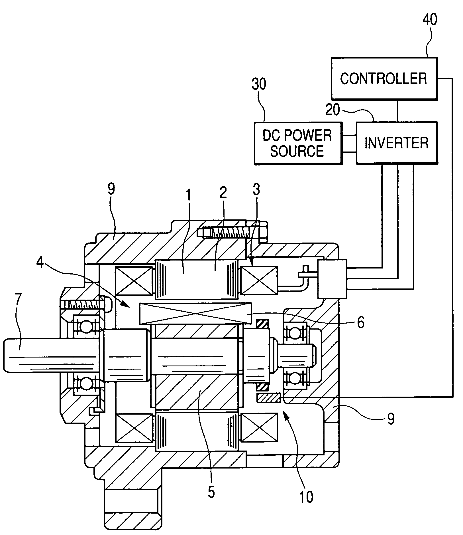
[0096]With reference to FIG. 1, a field-winding type of synchronous machine using armature-winding power supply technique according to a first embodiment of the present invention is described. FIG. 1 is a diagrammatic axial cross section of the field-winding type of synchronous machine (motor). This synchronous machine can be applied to hybrid vehicles, fuel cell vehicles, electric vehicles and the like as an on-vehicle driving power generating apparatus.

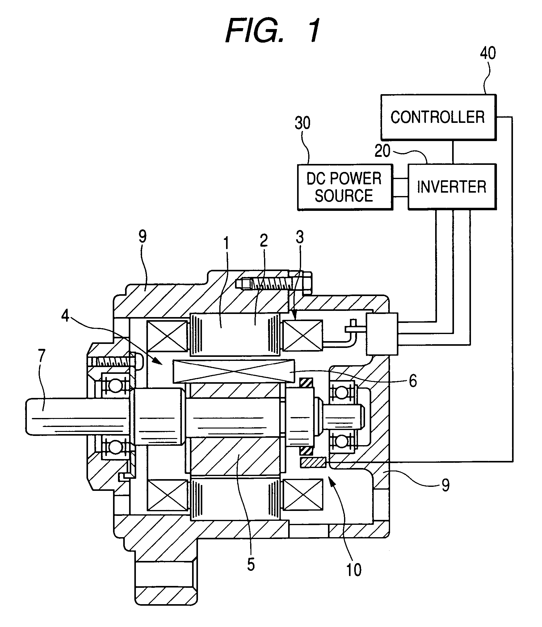
[0097]In FIG. 1, indicated by 1 is a stator, by 2 is a stator core, and by 3 is a stator winding (armature winding) wound about the stator core 2. Further, indicated by 4 is a rotor, by 5 is a rotor core, by 6 is a rotor winding (field winding) wound about the rotor core 5, and by 7 is a rotor shaft. Indicated by 9 is a frame (so-called housing) which is fixed to the stator 1 and rotatably supports the rotor 4. Indicated by 10 is a position sensor for detecting a rotational position of the rotor. The position sensor 10 is fixed to t...

second embodiment

[0104]With reference to FIG. 6, a field-winding type of synchronous machine using armature-winding power supply technique is described below. FIG. 6 shows a diagrammatic radial cross section of the field-winding type of synchronous machine (motor). In this embodiment, indicated by 8 are permanent magnets for producing field flux. The permanent magnet 8 produces field flux in the same direction as that of the field flux formed by the rotor winding 6. Thus, according to the present embodiment, the excitation assisted by the permanent magnets may suppress the increase of torque and reduce excitation current.

third embodiment

[0105]With reference to FIG. 7, a field-winding type of synchronous machine using armature-winding power supply technique, according to a third embodiment is described. In this embodiment, a capacitor 14 is connected parallel to the diode 12. This arrangement may stabilize the excitation current flowing through the rotor winding 6 and voltage generated therein. However, in the present embodiment, effective size of the field flux becomes small because, among the AC currents induced to the rotor winding 6, half-wave components of opposite phase that should be shut out are passed through the capacitor 14.


PUM


Abstract

A field-winding type of synchronous machine comprises a stator with an armature winding wound phase by phase, a rotor having a rotor core with a field winding wound, and a circuit enabling an armature current to pass the armature winding, the armature current corresponding to a synchronous current producing a rotation field rotating at an electrical-angle rotation speed agreeing to a rotation speed of the rotor. The synchronous machine further comprises a current suppressor and a current supplier. The current suppressor is connected to the field winging and suppresses, into a unidirectional current, an induced alternating current induced through the field winding in response to the armature current passing the armature winding. The current supplier supplies, phase by phase, to the armature winding a rotor exciting current whose waveform is different from the synchronous current only during a predetermined period of time shorter than one cycle of the synchronous current.

Description

CROSS-REFERENCE TO RELATED APPLICATIONS[0001]This application is based on and claims the benefit of priorities from earlier Japanese Patent Application No. 2005-188184 filed on Jun. 28, 2005, Japanese Patent Application No. 2005-338842 filed on Nov. 24, 2005, Japanese Patent Application No. 2005-353890 filed on Dec. 7, 2005 and Japanese Patent Application No. 2006-137929 filed on May 17, 2006 the descriptions of which are incorporated herein by reference.BACKGROUND OF THE INVENTION[0002]1. Technical Field of the Invention[0003]The present invention relates to a field-winding type of synchronous machine, and more particularly relates to an improvement of a structure for supplying electric power to a rotor winding (hereinafter also referred to as a field winding or a short-circuit winding) in a rotor-winding synchronous machine in which DC current is passed through a rotor.[0004]2. Related Art[0005]A rotary electric machine whose rotor rotates in synchronization with a rotating field ...

Claims


Application Information

Patent Timeline
Patent Type & Authority Patents(United States)
IPC IPC(8): H02P6/10H02P27/08H02P7/298
CPCH02K19/28H02K21/042H02P25/026H02K21/14H02P25/03
Inventor SEGUCHI, MASAHIRONOMURA, YURIOTSUJI, HIROYA
Owner DENSO CORP
Why Eureka
Try Eureka