

Electron beam recorder and electron beam irradiation position detecting method
a technology of electron beam and position detection, which is applied in the field of electron beam recorder and electron beam position detection method, can solve the problems of extremely difficult to detect and correct the variations of the position of the electron beam, and the method cannot be used
- Summary
- Abstract
- Description
- Claims
- Application Information
AI Technical Summary
Benefits of technology
Problems solved by technology
Method used
Image

Examples
first embodiment
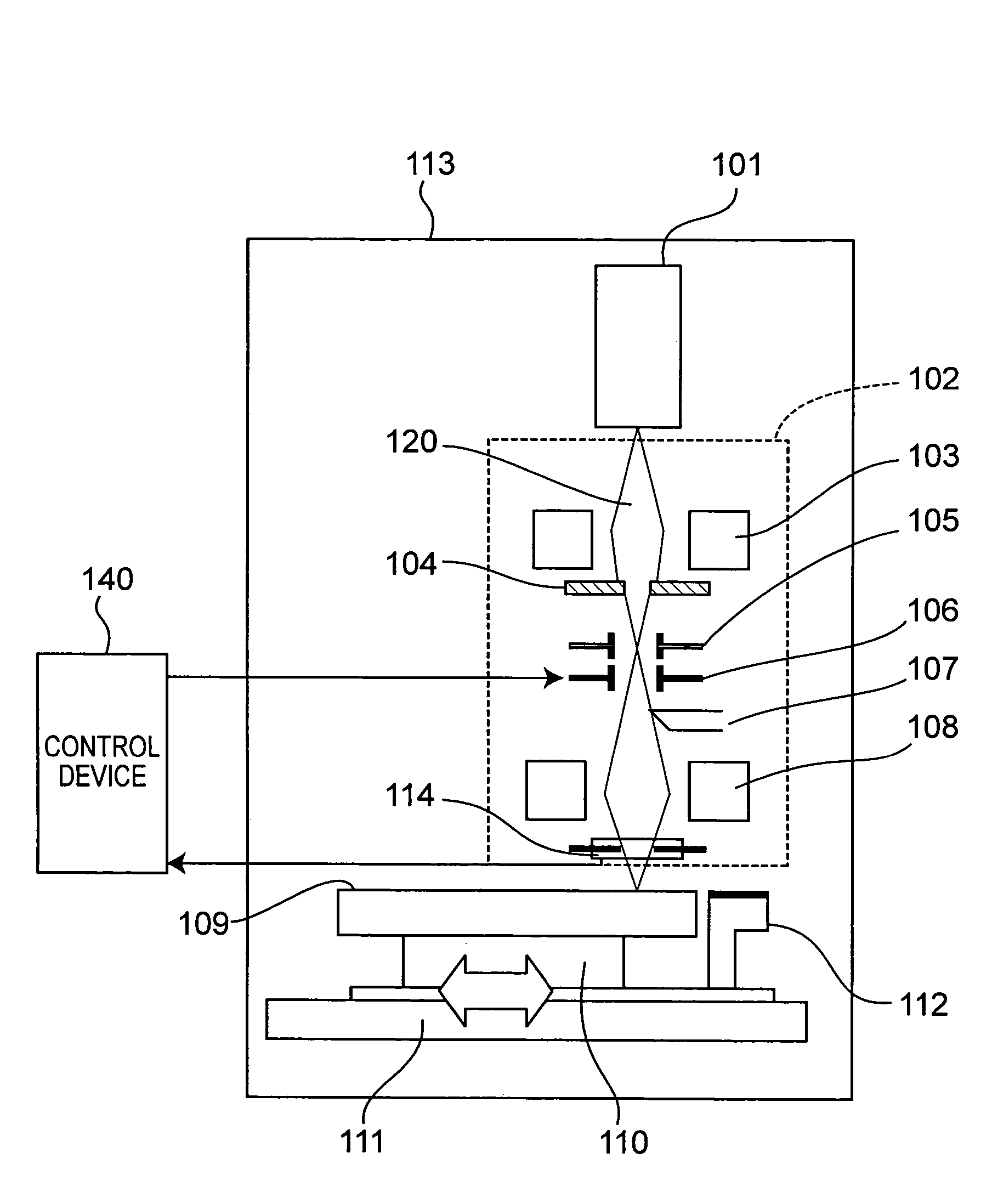
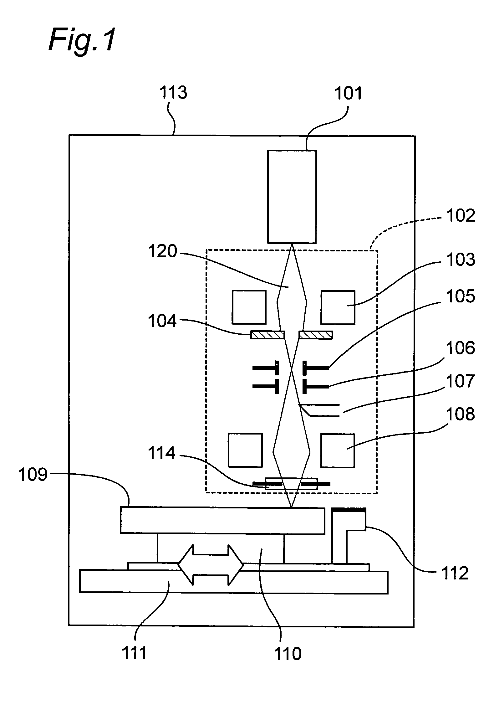
[0036]FIG. 1 shows an arrangement of an electron beam recorder for recording signals on a master 109 of an information recording medium, for example, an optical disc by using an electron beam 120, according to a first embodiment of the present invention. This electron beam recorder has a following arrangement portion similar to that of a conventional electron beam recorder of FIG. 15. Namely, this electron beam recorder includes an electron beam source 101 for generating an electron beam 120 and an electron optical system 102 which converges the emitted electron beam 120 onto the resist master 109 so as to record information patterns on the resist master 109 in accordance with inputted information signals. The electron beam source 101 and the electron optical system 102 are accommodated in a vacuum chamber 113.
[0037]The electron beam source 101 is constituted by a filament for emitting electrons upon flow of electric current therethrough, an electrode for suppressing the emitted ele...
second embodiment
[0054]FIG. 7 shows an arrangement of an electron beam recorder according to a second embodiment of the present invention. In the electron beam recorder of the second embodiment, the aperture 104 of the electron beam recorder of the first embodiment is eliminated and the electron beam irradiation position detecting unit 114 of the electron beam recorder of the first embodiment is replaced by an electron beam irradiation position detecting unit 214. Since other constructions of the electron beam recorder of the second embodiment are similar to those of the electron beam recorder of the first embodiment, the description is abbreviated for the sake of brevity. As shown in FIG. 8, the electron beam irradiation position detecting unit 214 includes a shielding plate 222 and a hole 221 for determining a beam diameter of the electron beam 120 is provided at a center of the shielding plate 222 in the feed direction X of the horizontally traveling stage 111 and the rotational direction Y of th...
third embodiment
[0061]FIG. 10 shows an arrangement of an electron beam recorder according to a third embodiment of the present invention. In the electron beam recorder of the third embodiment, the electron beam irradiation position detecting unit 114 of the electron beam recorder of the first embodiment is replaced by an electron beam irradiation position detecting unit 314. Since other constructions of the electron beam recorder of the third embodiment are similar to those of the electron beam recorder of the first embodiment, the description is abbreviated for the sake of brevity. The electron beam irradiation position detecting unit 314 includes magnetic field sensors 315 and 316 for detecting intensity of magnetic field generated about a central axis located at an optical axis of the electron beam 120 in the electron optical system 102. The magnetic field sensors 315 and 316 each formed by a coil are spaced a substantially identical distance from the optical axis of the electron beam 120 and co...
PUM
| Property | Measurement | Unit |
|---|---|---|
| luminescent | aaaaa | aaaaa |
| time | aaaaa | aaaaa |
| diameter | aaaaa | aaaaa |
Abstract
Description
Claims
Application Information