
Electronic apparatus and lighting device

a technology of electronic equipment and lighting devices, which is applied in the direction of electrical equipment construction details, lighting and heating equipment, printed circuit manufacturing, etc., can solve the problems of high humidity in the lighting device that lights the discharge lamp disposed in the luminaire of this purpose, large number of assembling steps of the lighting device, and increase in cost, so as to improve the workability of assembling

Inactive Publication Date: 2008-04-22
TOSHIBA LIGHTING & TECH CORP
View PDF5 Cites 66 Cited by
  • Summary
  • Abstract
  • Description
  • Claims
  • Application Information

AI Technical Summary

Benefits of technology

The design provides a compact, cost-effective, and easily assembled waterproof electronic apparatus capable of withstanding humid environments while efficiently radiating heat, reducing assembly time and costs.

Problems solved by technology

A lighting device that lights a discharge lamp disposed in the luminaire of this purpose may be exposed to high humidity.
Besides, in addition to time and labor of assembling the inverter controlled lighting device, the followings are necessary: time and labor of housing the lighting device in the cylindrical housing case, and time and labor of subsequently attaching the side plate to the housing case to assemble the waterproof case.
Thus, the number of assembling steps of the lighting device is large.
In consequence, use of the large waterproof case leads to a cost increase.
Besides, assembling is costly, and thus costs are high.
Furthermore, heat must be radiated from the lighting device because its use has been accompanied by heat generation.

Method used


Image

  • Electronic apparatus and lighting device
  • Electronic apparatus and lighting device
  • Electronic apparatus and lighting device

Examples


first embodiment

[0067]the present invention will be described with reference to FIGS. 1 to 14.

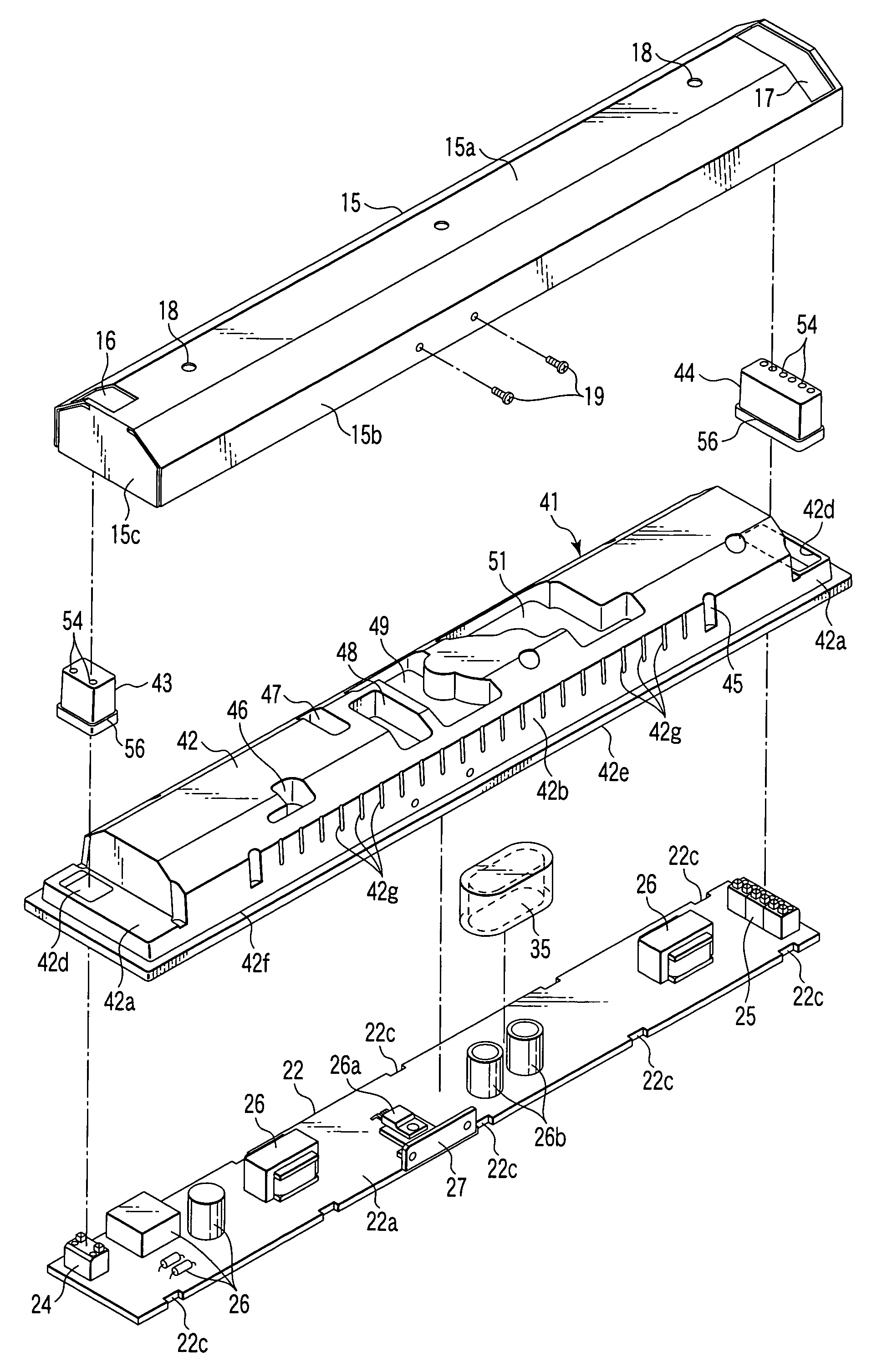
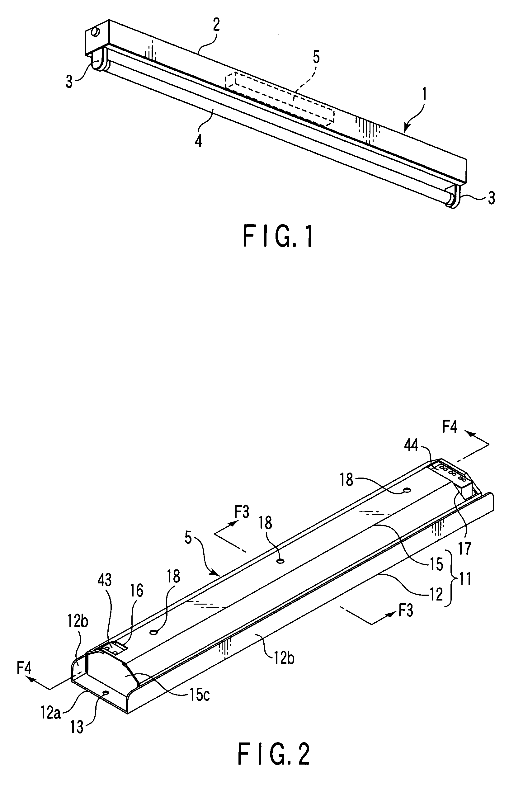
[0068]Referring to FIG. 1, a reference numeral 1 denotes a luminaire which comprises an electronic ballast (described later) to function as an electronic apparatus. The luminaire 1 is used as an outdoor lamp, a tunnel lamp installed in a tunnel, a lamp under the eaves of a station house, or the like having preferable waterproof properties. This luminaire 1 comprises a chassis 2, a lamp socket 3, a discharge lamp, a waterproof lighting device 5. For the discharge lamp, for example, a straight tube type fluorescent lamp 4 is used. For the lighting device 5 that lights the fluorescent lamp 4, a waterproof electronic apparatus such as an electronic ballast is used.

[0069]The chassis 2 illustrated in FIG. 1 is made of a metal and formed into a rectangular parallelepiped shape. For example, lamp sockets 3 are disposed in both longitudinal ends of the chassis 2 to project downward. The fluorescent lamp 4 is detach...

second embodiment

[0146]FIGS. 15 to 17 show the present invention. The second embodiment is similar to the first embodiment except for the followings. Accordingly, components identical or functionally similar to those of the first embodiment will be denoted by reference numerals similar to those of the first embodiment, and description thereof will be omitted.

[0147]According to the second embodiment, some raised bottoms 48, 49, and 51 individually comprise grooves 48a, 49a, and 51a. Lengths of these raised bottoms 48, 49, and 51 which cross a cover 15 are larger than those of the other raised bottoms.

[0148]The groove 48a crosses the raised bottom 48. Both ends of the groove 48a are opened to two among sides of the raised bottom 48. Preferably, as shown in FIG. 15, both ends of the groove 48a are opened to two sides corresponding to a longitudinal direction of a tray 41.

[0149]The groove 49a crosses the raised bottom 49. Both ends of the groove 49a are opened to two among sides of the raised bottom 49....

fourth embodiment

[0158]FIGS. 19 to 22 show the present invention. The fourth embodiment is similar to the first embodiment except for the followings. Accordingly, components identical or functionally similar to the first embodiment will be denoted by reference numerals similar to those of the first embodiment, and description thereof will be omitted.

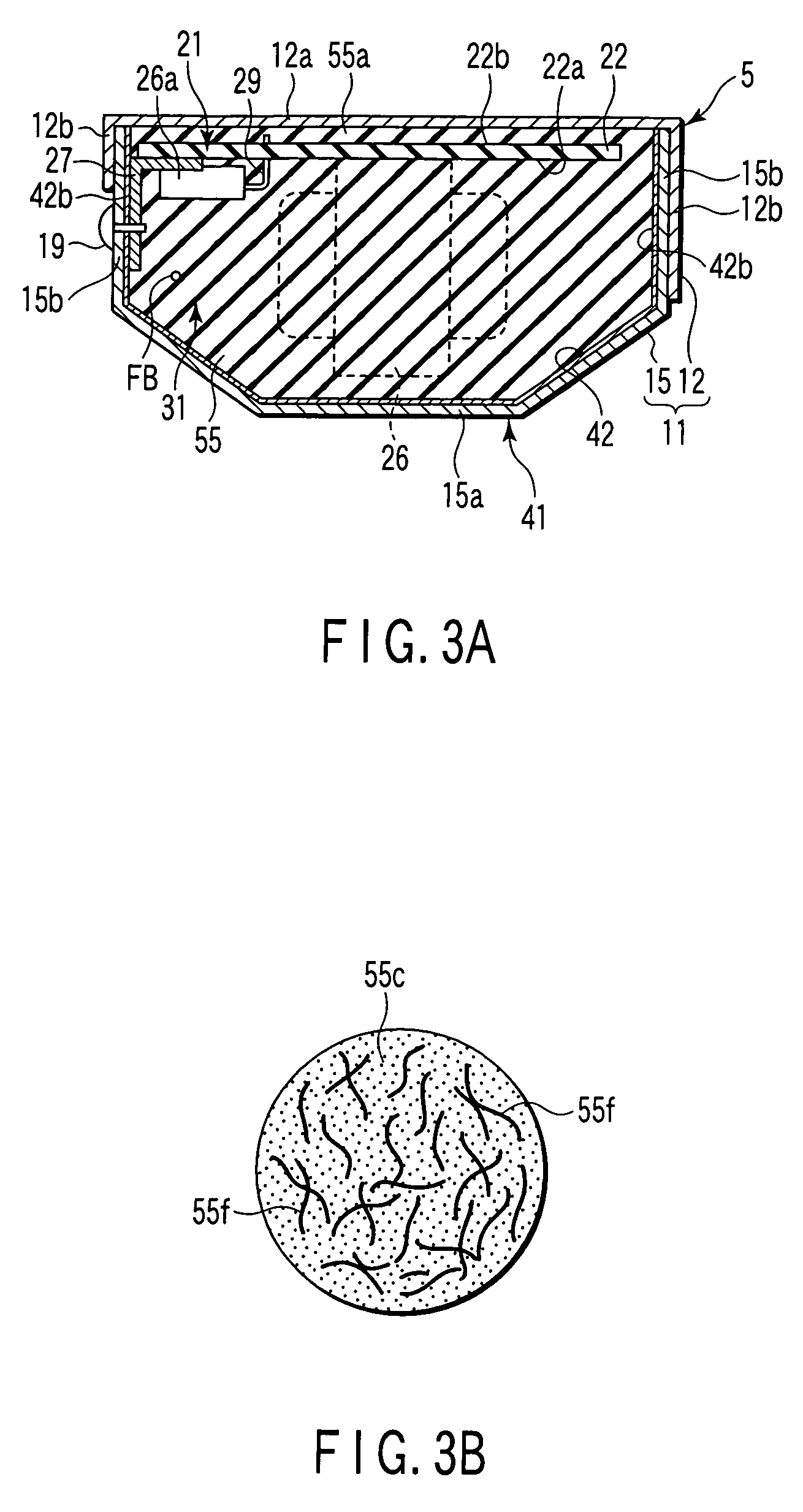
[0159]According to the fourth embodiment, the component cap of the first embodiment is not used. Thus, as shown in FIGS. 19 and 22A, a filling material 55 is brought into direct contact with an electrolytic capacitor 26b mounted on a circuit board 22 to bury the capacitor 26b therein. As shown in FIG. 21, the electrolytic capacitor 26b comprises an explosion-proof valve 28 in its tip surface. The explosion-proof valve 28 is destroyed when inner pressure abnormally increases in the electrolytic capacitor 26b.

[0160]Hardness of the filling material 55 heated to be hardened after filling is preferably set to hardness to enable a movement of the explosion-pr...


PUM


Abstract

There is disclosed an electronic apparatus which comprises a circuit module, a tray, and a filling material. The module comprises an electric insulating circuit board, and a plurality of electric components mounted on the board. The tray houses the module. The tray includes a raised bottom formed to project toward the circuit board. The filling material has waterproof properties and electric insulation. The circuit board and the electric components are buried to fill the tray with the filling material.

Description

CROSS-REFERENCE TO RELATED APPLICATIONS[0001]This application is based upon and claims the benefit of priority from prior Japanese Patent Applications No. 2004-234769, filed Aug. 11, 2004; No. 2004-234770, filed Aug. 11, 2004; No. 2004-300931, filed Oct. 15, 2004; No. 2005-169855, filed Jun. 9, 2005; and No. 2005-169856, filed Jun. 9, 2005, the entire contents of all of which are incorporated herein by reference.BACKGROUND OF THE INVENTION[0002]1. Field of the Invention[0003]The present invention relates to a waterproof electronic apparatus, and a lighting device which comprises the electronic apparatus to light a discharge lamp.[0004]2. Description of the Related Art[0005]There is a luminaire installed outdoors or under a highly humid environment. A lighting device that lights a discharge lamp disposed in the luminaire of this purpose may be exposed to high humidity. Accordingly, waterproof properties are required of the lighting device.[0006]For the lighting device, an inverter co...

Claims


Application Information

Patent Timeline
Patent Type & Authority Patents(United States)
IPC IPC(8): F21V23/02
CPCF21V23/026F21V31/04H05K3/284Y10S439/936
Inventor OKA, SHIGEHARUKOHARI, KENICHIARAKI, TSUTOMUSUZUKI, KOJIKOSA, KIYOTERUOGINO, DAISUKEKARASAWA, SHINICHI
Owner TOSHIBA LIGHTING & TECH CORP
Learn More