Sliding component and method for manufacturing the same

a technology of sliding components and components, applied in metal-working equipment, welding/cutting media/materials, soldering media, etc., can solve the problems of high risk of wear, large wear of bearings, and affecting durability, so as to reduce frictional resistance, reduce wear, and improve durability.

Active Publication Date: 2008-04-22
DIAMET CORP
View PDF9 Cites 5 Cited by
  • Summary
  • Abstract
  • Description
  • Claims
  • Application Information

AI Technical Summary

Benefits of technology

[0012]According to the above-described structure, the flat powder particles of copper or copper alloy are employed, and filled into the filling portion of the mold together with other material powder(s), allowing the flat powder particles to segregate on the surface of the sliding component, using vibration, electrostatic force, magnetic force or the like, whereby the sliding component thus obtained can have its surface covered with copper, generating a concentration gradient in which the copper-to-iron ratio thereof decreases from the surface of the sliding component toward the inside thereof while increasing the ratio of iron. Therefore, in a case that the bearing is formed from this sliding component, a rotation body is allowed to slide on the surface covered with copper with a reduced frictional coefficient between the rotation body and the surface, and thus a smooth rotation can be realized, while ensuring predetermined strength and durability by virtue of iron. Moreover, according to the above-described structure, even though the surface on which the rotation body slides wears, the sliding portions can maintain superior durability since copper is contained at the predetermined ratios under the worn surface.
[0014]Moreover, in the above-described sliding component, the surface coverage of copper in the sliding portion of the sliding component may be greater than or equal to 60%. Thus, the frictional resistance between the sliding surfaces can be dramatically decreased. More preferably, such surface coverage of copper may be greater than or equal to 90%.
[0017]According to the above-described structure, the flat powder particles of copper or copper alloy are employed, and then filled into the filling portion of the mold together with other material powder(s), allowing the flat powder particles to segregate on the surface of the sliding component, using vibration, electrostatic force, magnetic force or the like, whereby the obtained sliding component is covered with copper, generating a concentration gradient in which the copper-to-iron ratio decreases from the surface of the sliding component toward the inside thereof while increasing the ratio of iron, and thus the sliding component can have reduced frictional coefficient as well as superior durability.
[0020]Further, in the above-described method, the proportion of the flat powder particles may be in the range of 20 to 70% by weight of the entire material powders. If the proportion of the flat powder particles is less than 20% by weight, then the proportion of copper segregating toward the surface decreases, and thus frictional resistance becomes large. On the other hand, if the proportion of the flat powder particles is over 70% by weight, then the proportion of copper becomes too large to obtain superior strength. Accordingly, by employing the above-described range, the sliding component having reduced frictional resistance as well as superior strength can be obtained. More preferably, the proportion of the flat powder particles may be in a range of from 20 to 40% by weight.
[0021]Still further, according to the above-described method, the average value of the maximum projected areas of the flat powder particles may be at least three times as large as that of the maximum projected areas of the particles of the iron-based material powder. Due to such large difference in the maximum projected area, segregation is easy to take place, facilitating each particle's flat surface of the flat powder particles being disposed along a surface defining the surrounding of the filling portion. By applying vibration or the like in that condition, the flat powder particles are allowed to be more easily disposed along the surface defining the surrounding of the filling portion so that copper is allowed to easily segregate on the surface of the green compact.

Problems solved by technology

However, since an iron-based material such as steel is generally used for a rotation shaft, frictional resistance becomes large due to the same types of materials being used for both of the bearing and the rotation shaft so that a fused wear is very likely to occur, thus impairing durability thereof.
On the contrary, if copper-based material powder is used, frictional resistance between the bearing and the rotation shaft becomes significantly small, but a wear of the bearing becomes large, and thus durability thereof is also impaired.
For instance, noiselessness in initiating the rotation of a rotation shaft in such a low-temperature state as low as minus 40 degrees centigrade is required, which, however, has been difficult for the conventional ones to meet.

Method used


Image

  • Sliding component and method for manufacturing the same
  • Sliding component and method for manufacturing the same
  • Sliding component and method for manufacturing the same

Examples


Embodiment Construction

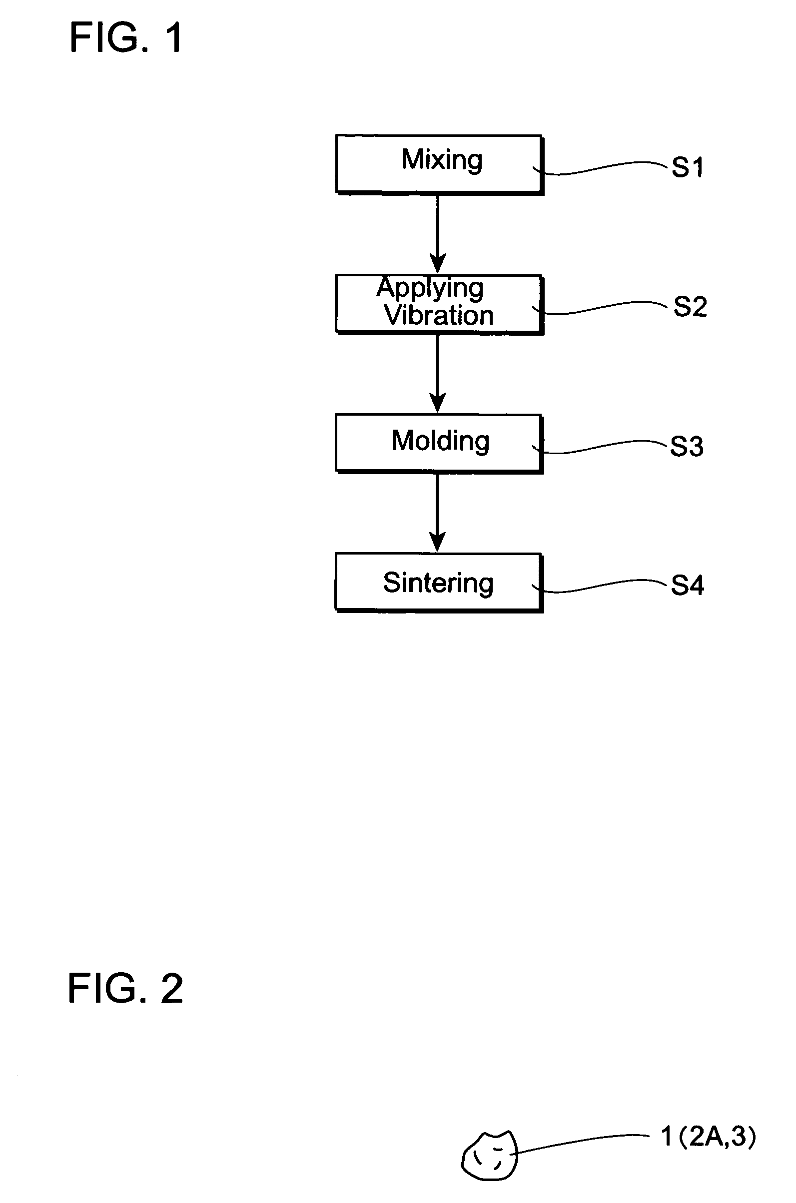
[0030]Preferred embodiments of the present invention will now be explained in detail with reference to accompanying drawings. FIGS. 1 to 8 show an embodiment of the present invention.

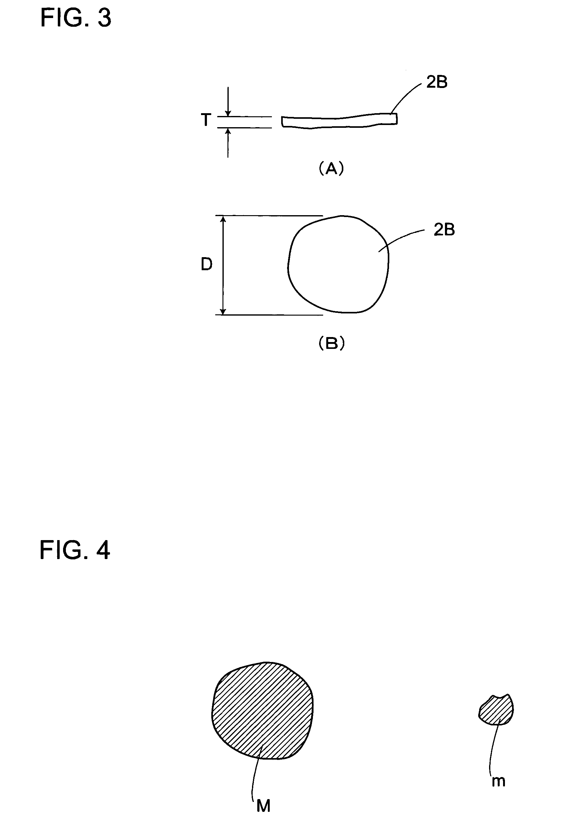
[0031]First, a method for manufacturing a sliding component according to an embodiment of the present invention will now be explained. An iron-based material powder 1, a copper-based material powder 2 and a small amount of an other material powder 3 are mixed as materials in a predetermined proportion (Step S1). For the iron-based material powder 1, a powder composed of substantially spherical and irregular particles such as atomized powder is used as shown in FIG. 2. For the copper-based material powder 2, an irregular-particle powder 2A and a flat powder particles 2B are used as shown in FIGS. 2, 3A and 3B.

[0032]An iron or iron alloy powder is used as the iron-based material powder 1, while copper or copper alloy powder is used as the copper-based material powder 2. Tin, carbon, phosphorus or zinc pow...


PUM

PropertyMeasurementUnit
aspect ratioaaaaaaaaaa
temperatureaaaaaaaaaa

Abstract

A bearing is manufactured by filling iron-based material powder and copper-based material powder in a filling portion of a mold, compacting those material powder so as to form a green compact, and then sintering the green compact. The copper-based material powder contains flat powder particles, the flat powder particles having a large aspect ratio than particles of the iron-based material powder. The coppers-based powder particles segregate on a sliding surface by vibration. The sliding surface of a bearing is covered with copper, and a ratio of iron increases from the sliding surface toward the inside. Since a rotation shaft slides on the sliding surface covered with copper, a frictional coefficient between the rotation shaft and the sliding surface is reduced, thus enabling a smooth rotation thereof. Simultaneously the usage of iron imparts predetermined strength and durability.

Description

CROSS-REFERENCE TO PRIOR APPLICATION[0001]This is a U.S. National Phase application under 35 U.S.C. §371 of International Patent Application No. PCT / JP2003 / 009862 filed Aug. 4, 2003, and claims the benefit of Japanese Patent Application No. 2002-249692 filed Aug. 28, 2002 both of which are incorporated by reference herein. The International Application was published in Japanese on Mar. 11, 2004 as WO 2004 / 020129 A1 under PCT Article 21(2).BACKGOUND OF THE INVENTION[0002]1. Field of the Invention[0003]The present invention relates to a sliding component such as a bearing or the like and a method for manufacturing the same.[0004]2. Description of the Related Art[0005]Typically, a bearing which supports a rotation shaft is one of the representatives of this kind of sliding components, which is manufactured by a well-known method including the steps of compacting material powders mainly composed of metallic materials so as to form a green compact; and then sintering this green compact t...

Claims


Application Information

Patent Timeline
Patent Type & Authority Patents(United States)
IPC IPC(8): B22F3/12C22C33/02B22F5/00B22F1/05F16C33/12F16C33/14
CPCF16C33/14C22C33/0207F16C33/121B22F1/0011B22F2999/00Y10T428/12021Y10T428/12028B22F1/0003B22F2202/01B22F2207/01F16C2220/20B22F1/05B22F1/09B22F3/12B22F7/00
Inventor SHIMIZU, TERUOMARUYAMA, TSUNEO
Owner DIAMET CORP
Why Eureka
Try Eureka