COD measuring method and device

a technology of measuring method and cod, applied in the direction of photometry using electric radiation detectors, optical radiation measurement, instruments, etc., can solve the problem of failing to provide a desirable correlation to cod

Inactive Publication Date: 2008-04-22
SHIMADZU CORP
View PDF7 Cites 5 Cited by
  • Summary
  • Abstract
  • Description
  • Claims
  • Application Information

AI Technical Summary

Benefits of technology

[0028]In the COD measuring method and device of the present invention, an equation indicating the relationship between the total-absorbance and COD value is used as the COD conversion equation; therefore, different from the conventional COD conversion equation in which absorbance for a single wavelength in the ultraviolet region is used, the best suited COD conversion equation can be used depending on the kinds of organic substances contained in the sample water, and it becomes possible to obtain a converted COD value that hardly has relative error to the actual COD value.
[0029]In the case of industrial wastes, the initial correlation tends to vary due to a change in materials, amount of manufactured products and the like. When the correlation is changed, the COD conversion equation no longer becomes best suited, failing to provide a COD conversion value with high precision (high reliability). Therefore, a plurality of combinations of weighting factors are prepared, and among the plurality of COD conversion equations found with respect to the sample water to be measured, the equation having the best correlation is used as the COD conversion equation for the sample water; thus, it becomes possible to properly cope with such a change in sample water and water samples of various kinds.

Problems solved by technology

For this reason, the COD conversion equation, obtained by using absorbance in a single ultraviolet-ray wavelength, tends to fail to provide a desirable correlation to COD.

Method used


Image

  • COD measuring method and device
  • COD measuring method and device
  • COD measuring method and device

Examples


Embodiment Construction

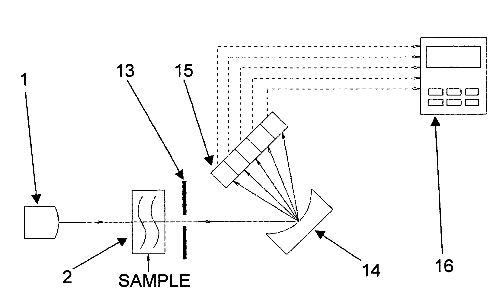
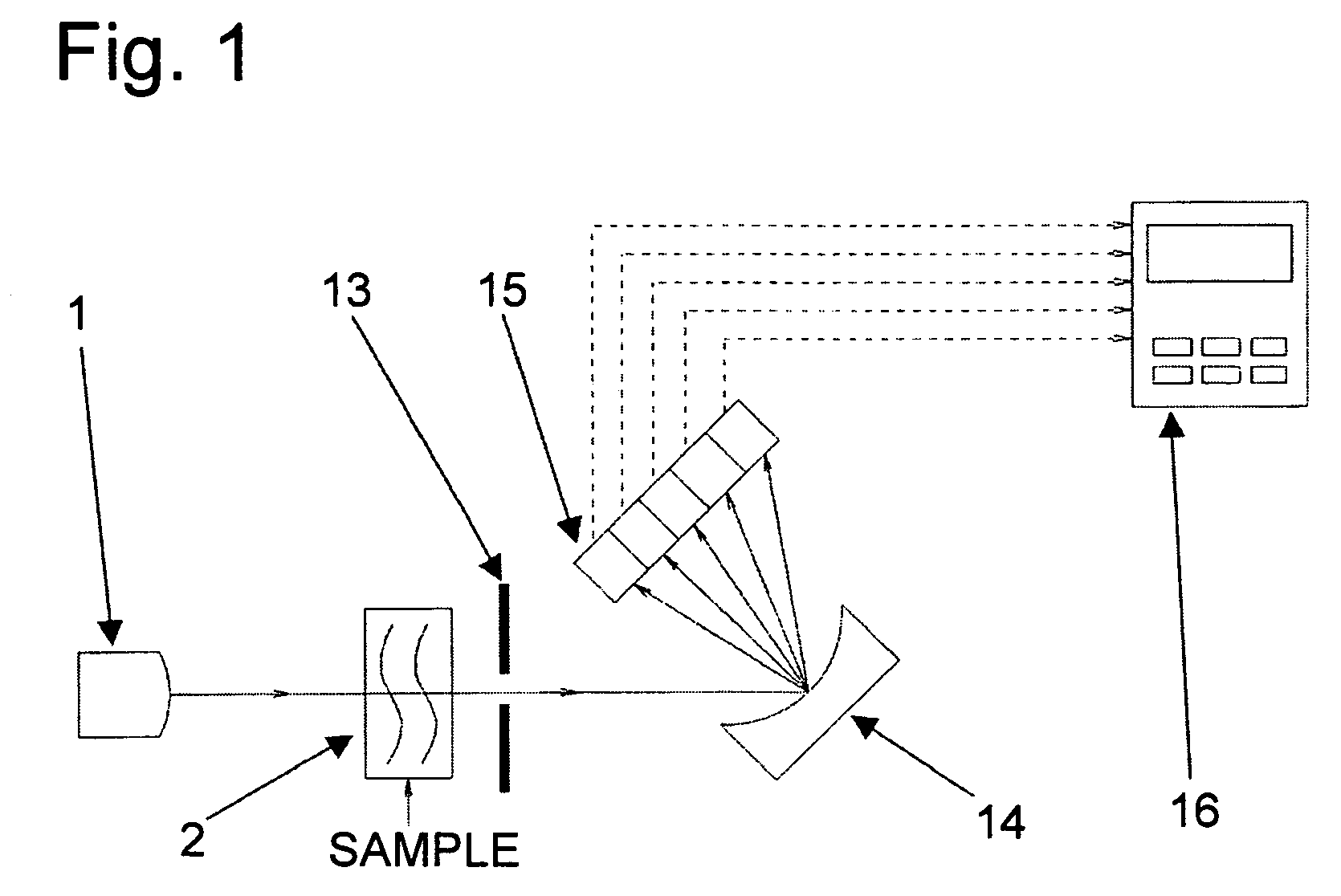
[0039]FIG. 1 is a schematic block diagram that shows one embodiment of an absorption photometer that can be used as a COD measuring device.

[0040]A light source that can emit continuous spectra covering an ultraviolet region and a visible region is preferably used as a light source 1. For example, a xenon lamp may be used. However, not limited to the xenon lamp, a mercury lamp that emits a plurality of luminescent line spectra covering the ultraviolet region and visible region may also be used as a light source. In the present embodiment, a light source such as a xenon lamp, which emits continuous spectra, is used.

[0041]A measuring cell 2 is a flow cell, and sample water is allowed to flow through it. The measuring cell 2 is made of synthetic quartz in its window member or in its entire cell so as to transmit light from the light source 1 through the sample water.

[0042]Reference numeral 14 indicates a grating that forms a spectrometer used for separating light having continuous spect...


PUM

PropertyMeasurementUnit
wavelengthsaaaaaaaaaa

Abstract

A COD conversion equation holding unit in a computing unit of a COD measuring device holds a COD conversion equation that indicates a relationship between total-absorbance that is linearly combined by multiplying an absorbance value at each of a plurality of wavelengths by a weighting factor and a COD value, and a conversion unit finds a converted COD value by using the COD conversion equation, and outputs the resulting value. Preferably, a COD conversion equation calculation unit calculates a COD conversion equation based upon the relationship between the total absorbent and an actual measured COD value in sample water, and a correlation calculation unit finds a correlation with respect to each of a plurality of COD conversion equations calculated by the COD conversion equation calculation unit. In this case, the COD conversion equation holding unit holds the conversion equation having the best correlation among the COD conversion equations calculated by the COD conversion equation calculation unit as a COD conversion equation for the sample water.

Description

BACKGROUND OF THE INVENTION[0001]1. Field of the Invention[0002]The present invention relates to a COD (chemical oxygen demand) measuring method which forms a COD conversion equation (regression equation) used for converting a ultraviolet-ray (UV) value to a COD value on the basis of the correlation between UV absorbance and a COD measured value in drainage, environmental water and the like, and based upon this conversion equation, provides a converted COD value from a UV value measured in sample water, and also concerns a device for such a method.[0003]Here, COD is treated as a factor that includes BOD (biological oxygen demand).[0004]2. Description of the Related Art[0005]The Japanese Industrial Standard (JIS) has stipulated the ultraviolet photometer for monitoring of water pollution for use in water-quality monitoring, and the UV measured value is used in correlation with the COD value for calculating a water pollution loading amount and the like in connection with the total pol...

Claims


Application Information

Patent Timeline
Patent Type & Authority Patents(United States)
IPC IPC(8): G01N21/00
CPCG01N21/33G01N33/1806G01N33/1893
Inventor ITABASHI, TOSHIHISAMORITA, YOZO
Owner SHIMADZU CORP
Why Eureka
Try Eureka