Biomagnetic measurement apparatus

a technology of biomagnetic measurement and apparatus, which is applied in the direction of magnetic variable regulation, instruments, applications, etc., can solve the problems of discontinuous values, time-consuming and labor-intensive job of obtaining a pcam from images, and coming to aris

Active Publication Date: 2008-04-22
HITACHI HIGH-TECH CORP
View PDF10 Cites 12 Cited by
  • Summary
  • Abstract
  • Description
  • Claims
  • Application Information

AI Technical Summary

Benefits of technology

[0013]Under such circumstances, the primary object of the present invention is to provide a biomagnetic measurement apparatus capable of projecting the current distributions at front and back measurement regions and the distributions of the amplitudes of those current distributions, on a three-dimensional standard heart model seamlessly, and thereby visualizing the cardiac electrical current distributions conforming to the cardiac morphology.
[0026](5a) adjusting the position of the sinus node and the estimated position of the current source so as to minimize the difference (first difference) between those positions in the data for representing a three-dimensional heart model;
[0027](5b) adjusting the positions of the left ventricle region and a region having an isointegral map exceeding a threshold value so as to minimize the difference (second difference) between the left ventricle region and the region having the isointegral map exceeding the threshold value in the data for representing the three-dimensional heart model;
[0028](5c) adjusting the position of the sinus node and the estimated position of the current source, as well as the positions of the left ventricle region and the region having an isointegral map value exceeding a predetermined value so as to minimize the first difference in (5a) and the second difference in (5b); and
[0029](5d) adjusting the positions of the current distributions in two directions obtained from (1) and / or distributions of the absolute values of those current distributions by changing the assumption of the moment, direction, and position of one current source in the above (4) so as to minimize the difference between the positions of the current distributions in two directions obtained from (1) and / or distributions of the absolute values of those current distributions.
[0039]According to the invention, it is possible to determine an optimal position of a standard heart model for healthy subjects and subjects with heart disease from the cardiac magnetic field data and to obtain a three-dimensional cardiac-current distribution image that includes cardiac morphology information without requiring any of MRI and X-ray CT measurements. It is also possible to adjust the base levels of current values into one so as to link both front and back CAMs continuously and project the current distribution at the front side and the distribution of the amplitude of the current distribution, as well as the weighted back side current distribution and the distribution of the amplitude of the current distribution on the standard heart model or heart model of each subject, thereby obtaining continuous three-dimensional cardiac-current distribution images over the whole heart.

Problems solved by technology

However, when applying such a method actually, there are two problems coming to arise.
The first problem is that MRI and X-ray CT images need to be obtained for each subject, making it time-consuming job to obtain a PCAM from the images.
The second problem is that because the base level between CAM current values obtained from the front and back measurement regions depends on a distance between the heart and the measurement surface (front or back), discontinuous values occurs in PCAM at a junction between the front and back surface of the heart model measurement regions.

Method used


Image

  • Biomagnetic measurement apparatus
  • Biomagnetic measurement apparatus
  • Biomagnetic measurement apparatus

Examples


first embodiment

[0070]In this first embodiment, an average value of the sizes of the hearts for three healthy subjects is used to create a three-dimensional standard heart model to be applied to a plurality of subjects. Although a standard heart model is created from image data of three healthy subjects in this first embodiment, it is also acceptable to create the model from the image data of only one healthy subject or those of two or more healthy subjects.

[0071]FIG. 4 explains the first embodiment by illustrating a measurement region of a nuclear magnetic resonance imaging apparatus (MRI apparatus, hereinafter). The measurement region 14 of the MRI apparatus is defined as a 300 mm×300 mm region located on the coronal plane of the chest wall (front side) of the subject. In order to visualize a three-dimensional heart structure, the measurement region 14 is moved in steps of 5 mm on the z axis to obtain MRI images of 1 mm in slice thickness. The standard heart model is created in the following step...

second embodiment

[0102]In the second embodiment, an optimal position of the standard heart model is determined using the coordinates of the left ventricle region as the heart position information. The left ventricle is a part that transfers blood to the aorta and its cardiac muscle is the thickest among the regions of cardiac muscle. The coordinates of this left ventricle can be found from an isointegral map of the T-wave that reflects a phase of the ventricle repolarization. The isointegral map mentioned here is obtained by integrating the amplitude of the cardiac electrical current distribution for the arbitrary time interval. An isointegral map can be calculated by the expression 5 using CAMs.

Isum(x,y)=∫|It(x,y)|dt  (5)

[0103]The integral section in the expression 5 is between T1 and T2. The It(x, y) denotes a CAM at instant time t, which can be calculated by the expression 3. As shown in the expression 5, it is found that an isointegral map corresponds to a total sum of the amplitude of the cardi...

third embodiment

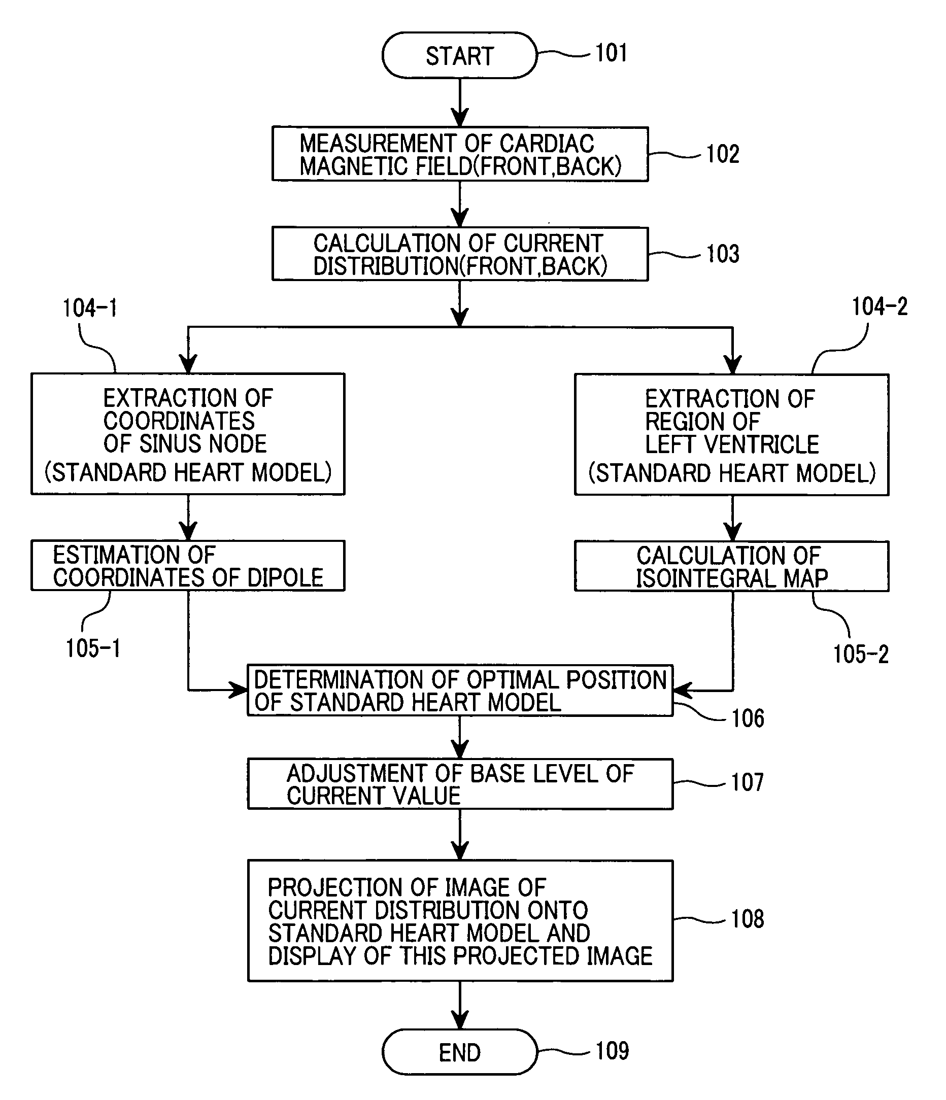
[0112]In this third embodiment 3, an optimal position of the standard heart model is determined using the coordinates of the sinus node and the coordinates of the left ventricle region as the information on the heart's position. The optimal position is determined in the following steps of (1) to (4).

[0113]FIG. 16 illustrates a method for extracting the left ventricle region of the three-dimensional standard heart model and a method for setting the coordinates of the sinus node on the standard heart model.

[0114]FIG. 17 illustrates a region extracted from an isointegral map and estimated dipole coordinates, in the third embodiment of the invention.

[0115](1) As shown in FIG. 16, the two-dimensional region 38 of Z=Z0 is extracted from the three-dimensional standard heart model 15 (FIG. 14), then the coordinates 39 ((x0,k, y0,k), k=1, 2, . . . , K) of the left ventricle region consisting of DEF points are extracted. Then, the coordinates (xd, yd, zd) of the sinus node 16 are set on the s...


PUM


Abstract

Disclosed herein is a biomagnetic measurement apparatus capable of visualizing cardiac electrical current distributions with information on the cardiac morphology of a subject. A magnetic field component in the z direction, vertical to the chest surface of a subject, is measured from two directions, front and back of the chest, and then to calculate the current distributions in the two directions and the distributions of the amplitudes of those current distributions. A three-dimensional standard heart model is created from average data on the cardiac morphology obtained from plural healthy subjects. An optimal position of the model is determined using the coordinates of the sinus node and the coordinates of the left ventricle. Then, a weight coefficient is obtained by front and back current distributions and front and back the distributions of the amplitudes of those current distributions on a set boundary of the model.

Description

CLAIM OF PRIORITY[0001]The present application claims priority from Japanese application JP 2003-317705 filed on Sep. 10, 2003, the content of which is hereby incorporated by reference into this application.FIELD OF THE INVENTION[0002]The present invention relates to a biomagnetic measurement apparatus that uses superconducting quantum interference device (SQUID) magnetometers to measure a weak magnetic field generated from a human heart.BACKGROUND OF THE INVENTION[0003]Visualizing electrophysiological phenomena to occur in heart muscles is very important for diagnosing heart diseases such as ischemic heart diseases and arrhythmia. As one of the apparatuses that can visualize such electrophysiological phenomena, there is a biomagnetic measurement apparatus. The biomagnetic measurement apparatus can measure a weak magnetic field (heart magnetic field, hereinafter) generated from a human heart in a noninvasive and yet noncontact manner at many measurement points. The data obtained fro...

Claims


Application Information

Patent Timeline
Patent Type & Authority Patents(United States)
IPC IPC(8): A61B5/05G01R33/28A61B5/04A61B5/0452A61B5/055A61B6/03G06T1/00G06T15/00
CPCA61B5/04007A61B5/0044A61B5/243
Inventor OGATA, KUNIOMIKANDORI, AKIHIKOMIYASHITA, TSUYOSHITSUKADA, KEIJI
Owner HITACHI HIGH-TECH CORP
Why Eureka
Try Eureka