Chip discharge system

a discharge system and chip technology, applied in the direction of separation process, liquid displacement, filtration separation, etc., can solve the problems of dirty coolant, achieve the effect of facilitating processing, forming and/or cutting metals, and reducing the number of parts

Inactive Publication Date: 2008-04-29
MAYFRAN INT INC
View PDF18 Cites 13 Cited by
  • Summary
  • Abstract
  • Description
  • Claims
  • Application Information

AI Technical Summary

Benefits of technology

[0011]The present invention relates to a chip discharge system, and more particularly to a chip discharge system designed to at least partially remove chips of metal from a fluid. The invention is particularly directed to a chip discharge system to at least partially remove chips of metal from a dirty coolant, and will be particularly described with reference thereto; however, it will be appreciated that the invention has broader applications. When processing, forming, and / or cutting metals such as, but not limited to, aluminum, brass, copper, iron, magnesium, manganese, stainless steel, etc., and / or resin material, a coolant such as a cutting oil and / or lubricating oil is used to facilitate in the processing, forming, and / or cutting metals, and / or to extend the life of the machinery used to process, form, and / or cut metals. During the processing, forming, and / or cutting metals, metal chips are mixed with coolant resulting a dirty coolant. The dirty coolant is then charged into a dirty coolant treatment tank and the chips are separated from the coolant and scooped up to transport such chips out from the treatment tank. The present invention is an improvement over prior art chip discharge systems. The present invention is designed to overcome the foregoing drawbacks of prior art chip discharge systems. The present invention is directed to a chip discharge system that includes less parts, that is less expensive to assemble and maintain, and which improves the efficiency of chip removal from dirty coolant.

Problems solved by technology

During the processing, forming, and / or cutting metals, metal chips are mixed with coolant resulting a dirty coolant.

Method used


Image

  • Chip discharge system
  • Chip discharge system
  • Chip discharge system

Examples


third embodiment

[0048]Referring now to FIG. 6, the present invention is disclosed. FIG. 6 is a cross-sectional view of a chip discharge system 30 comprising a dirty coolant treatment tank 32. Positioned in the dirty coolant treatment tank is a rotating filtration drum 31 that receives dirty coolant D which is discharged from a machine tool or the like. The dirty coolant is filtered by a filtration medium 31a on filtration drum 31, and filtered coolant C is discharged through a coolant discharge opening 31b provided on a side wall of filtration drum 31. The filtered coolant is collected in an external clean coolant tank 34 for recycling, reuse and / or disposal. Chips K that are contained in dirty coolant D are trapped by on a surface of the filtration medium 31a of filtration drum 31 and scooped up by the filtration drum. The chips are subsequently scraped off the filtration drum by a rotating brush 33 which contacts or is positioned closely adjacent to the surface of the filtration drum 31. The rota...

fourth embodiment

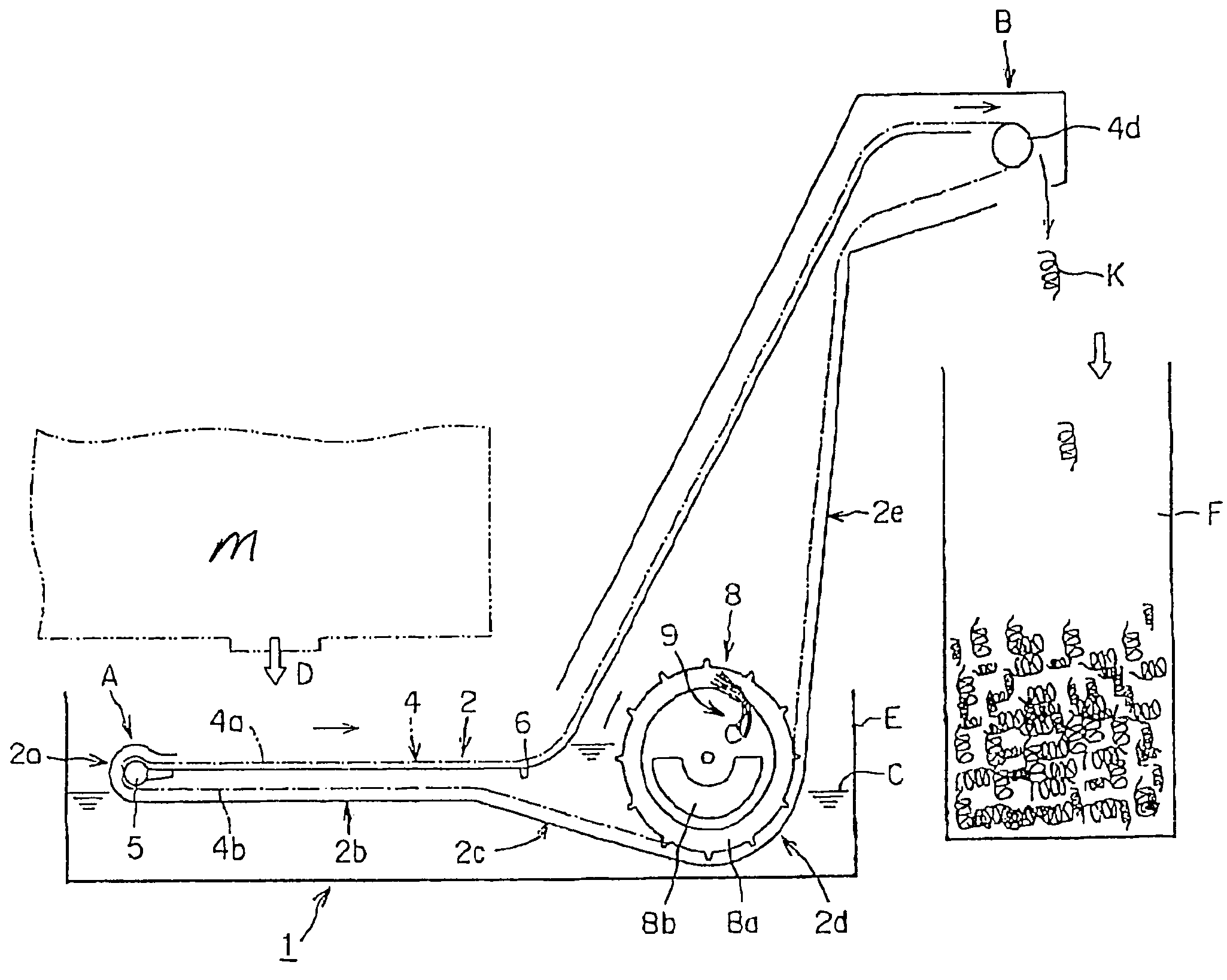
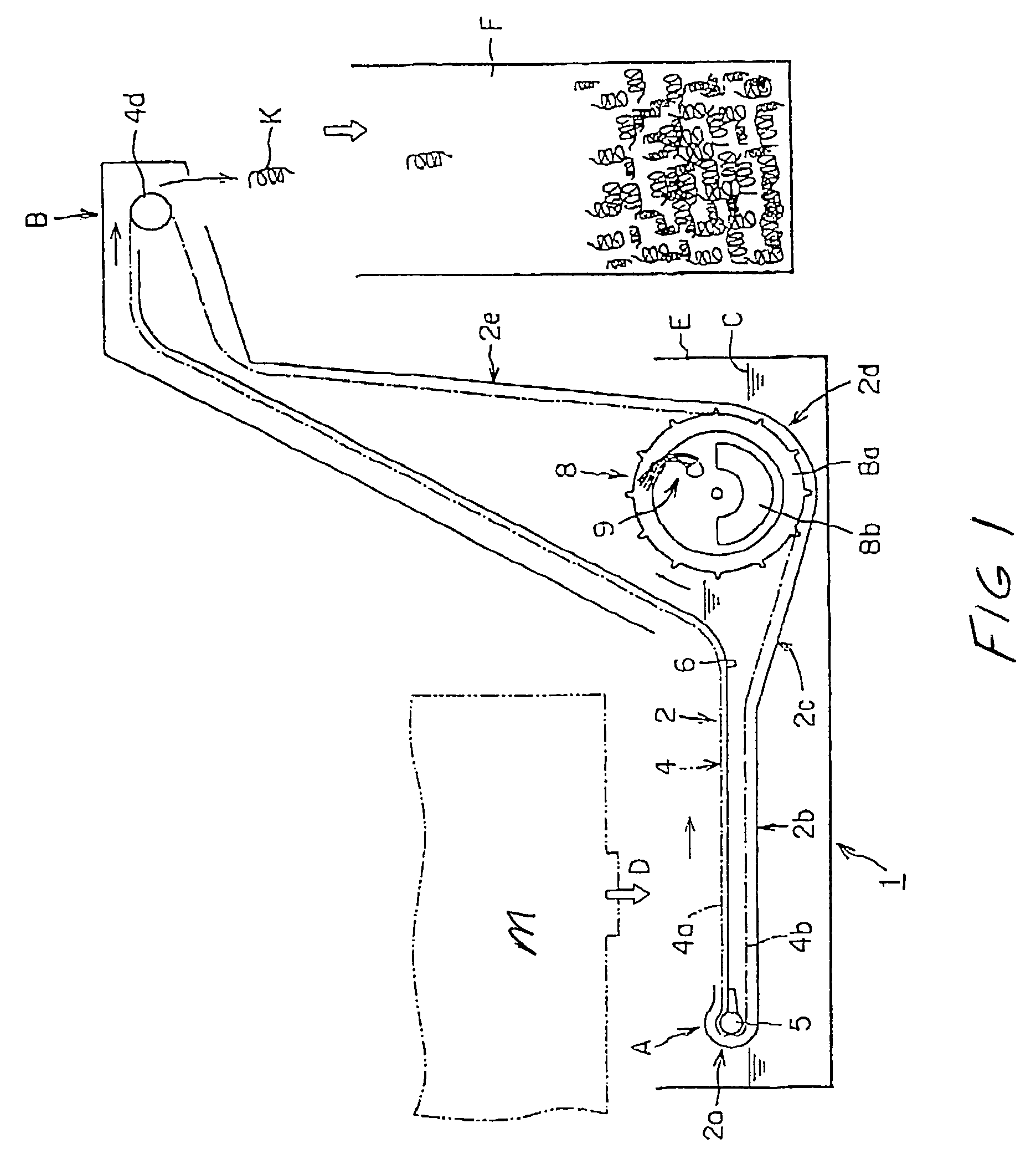
[0049]Referring now to FIG. 7, the present invention is disclosed. FIG. 7 illustrates a side view of a chip discharge system 40. The dirty coolant D containing chips is discharged from a machine tool M onto an inclined slope 41. The discharged dirty coolant is collected in a separating screen box 42, wherein the chips in dirty coolant D are caught and the filtered coolant is collected in a coolant tank 44 for recycling, reuse and / or disposal. A fluid dispersing means 49 is provided at upstream of the slope 41 to remove chips adhering to and retained on the surface of the slope. The structure and function of the fluid dispersing means is similar to the fluid dispersing means described with respect to FIG. 1-4.

[0050]In the present invention, the fluid dispersing means can be provided to inhibit or prevent a drum-like filtration medium provided in the dirty coolant tank as explained in the first and third embodiments from becoming clogged, and it can also be used to inhibit or prevent ...


PUM

PropertyMeasurementUnit
areaaaaaaaaaaa
shapeaaaaaaaaaa
angleaaaaaaaaaa

Abstract

A chip discharge system with a fluid dispersing means which inhibits clogging, which has a simple structure, which can spray out a uniformly-spreading flow, and which can adjust the momentum of dispersing flow without requiring an additional device.

Description

[0001]This patent application is a continuation of co-pending PCT patent application Serial. No. PCT / US / 03 / 06789 filed Mar. 7, 2003, which in turn claims priority on Japanese patent application Serial No. 2002-76694 filed Mar. 19, 2002.[0002]The present invention relates to a chip discharge system, and more particularly to a chip discharge system designed to at least partially remove chips of metal from a fluid. The invention is particularly directed to a chip discharge system to at least partially remove chips of metal from a dirty coolant, and will be particularly described with reference thereto; however, it will be appreciated that the invention has broader applications.BACKGROUND OF THE INVENTION[0003]During a metal working or a resin finishing process such as when cutting or grinding is performed by a machine tool, the machine tool discharges coolant and chips of metal or resin of assorted sizes. Common metal that are cut and / or machined include aluminum, brass, copper, iron, ...

Claims


Application Information

Patent Timeline
Patent Type & Authority Patents(United States)
IPC IPC(8): E03C1/04B23Q11/00
CPCB23Q11/0057Y10T409/304088Y02P70/10
Inventor NISIGUCHI, SHIGERU
Owner MAYFRAN INT INC
Why Eureka
Try Eureka