Method of producing the keytop for pushbutton switch

a technology of keytops and pushbutton switches, applied in the field of keytops, can solve the problems of dust likely to adhere during coating, thin metal layer formed by vapor deposition or sputtering, and wear, and achieve the effects of low cost, good yield and rich design

Inactive Publication Date: 2008-04-29
POLYMATECH CO LTD
View PDF33 Cites 8 Cited by
  • Summary
  • Abstract
  • Description
  • Claims
  • Application Information

AI Technical Summary

Benefits of technology

[0012]Therefore, with the foregoing in mind, it is an object of the present invention to provide a key top for a pushbutton switch having a sensation of metal, a rich design, a satisfactory yield, a low cost, the capability of being illuminated, and excellent durability.

Problems solved by technology

However, according to the method of the first prior art, the metal layer formed by vapor deposition or sputtering is thin.
Therefore, when a key top made of a resin is repeatedly pressed down, the metal layer wears away and may eventually disappear.
According to the former method, dust is likely to adhere during coating.
According to the latter method, the metal layer is likely to be cracked when the resin film is curved.
In both methods, the yield is poor and the cost is high.
Therefore, a display portion with minute and complicated designs cannot be realized and the cost is high.
According to the method of the third prior art, compared with the case where the metal layer is formed by plating, it is difficult to provide a smooth mirror surface, and wear resistance is not satisfactory.
According to the method of the fourth prior art, unless a laser treatment is conducted after plating, it is difficult to form, in particular, letters containing an island portion isolated from the periphery, such as digits “9” and “0”, and it is difficult to adjust a laser output for forming a display portion without influencing regions on the periphery of a letter, a symbol, or the like.
However, according to this method, in order to decrease a resistance of the conductive ink, it is required to use silver powder or copper powder, which makes the conductive ink expensive, resulting in a high cost.

Method used


Image

  • Method of producing the keytop for pushbutton switch
  • Method of producing the keytop for pushbutton switch
  • Method of producing the keytop for pushbutton switch

Examples


example 1 fig.3

Example 1 FIG. 3B

[0116]ABS resin (3001 MF, trade mark, produced by Mitsubishi Rayon Co., Ltd.) of a plating grade was dissolved in an organic solvent, cyclohexanone (Wako Pure Chemical Industries, Ltd.), whereby ABS resin ink containing 1000 parts by weight of cyclohexanone based on 100 parts by weight of the ABS resin was prepared for forming a base layer.

[0117]The above-mentioned ABS resin ink was pad-printed at a desired position on the surface of a key top body 11 made of a polycarbonate (PC) resin molded by injection molding. Thereafter, the organic solvent, cyclohexanone, was completely removed by a dryer at 80° C., whereby a base layer 12 was formed. The base layers 12 with the following thicknesses were formed: 3 μm to 5 μm, 8 μm to 10 μm, 13 μm to 15 μm, and 20 μm to 22 μm.

[0118]Next, the surface of the base layer 12 was defatted. Thereafter, the base layer 12 was soaked in an etchant containing chromic acid (400 g / l) and sulfuric acid (200 ml / l) at 70° C. for 2.5 minutes, ...

example 2 fig

[0121]Base layer ink was prepared in the same way as in Example 1, using ABS resin (3001 MF, trade mark, produced by Mitsubishi Rayon Co., Ltd.) of a plating grade. The base layer ink was screen-printed onto the surface of a polyethylene-based resin film 28 to form an insulating base layer 22. The thickness of the base layer 22 was 5 μm. Then, an acrylic-based ink was applied, as a polymer coating ink, to a desired position on the surface of the base layer 22 by pad printing to form a polymer coating layer 23. An adhesive layer 29 was formed on the reverse surface of the resin film 28, using a white urethane-based ink. The resin film 28 was curved with a die, and the curved convex portion was filled with PC resin, whereby a key top body 21 integrated with the resin film 28 was obtained. After an etching treatment, a nickel electroless plating layer 24 was formed by electroless plating on the surface of the base layer 22. The key top was attached to a keypad 26 via an adhesive layer ...

example 3 fig.8

Example 3 FIG. 8

[0123]First, 100 parts by weight of ABS resin (3001 MF, trade mark, produced by Mitsubishi Rayon Co., Ltd.) of a plating grade was dissolved in 1000 parts by weight of cyclohexanone, and 2 parts by weight of a fluorine type leveling agent (Schwego Flour 8038, produced by Brend Schwegmann) was further mixed in the solution to prepare an ABS resin coating.

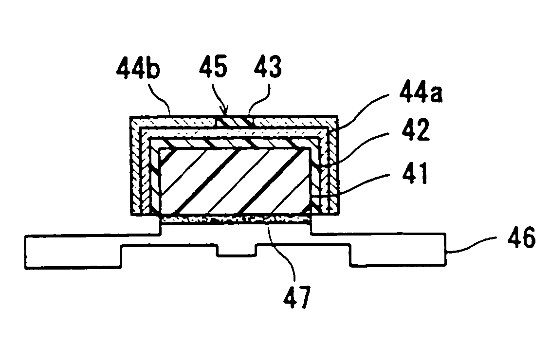
[0124]The ABS resin coating was applied by spray coating to the surface of a key top body 41 made of PC resin (polycarbonate resin) molded by injection molding. Thereafter, the ABS resin coating was dried by a box drier at 100° C. for 60 minutes to completely remove cyclohexanone, thereby forming a base layer 42 made of ABS resin with a thickness of 8 μm to 10 μm.

[0125]The surface of the key top on which the base layer 42 was formed was subjected to an etching treatment, and was coated with a catalyst. Thereafter, a nickel electroless plating layer 44a with a thickness of 30 nm was formed. On the surface of the electr...


PUM

PropertyMeasurementUnit
transmittanceaaaaaaaaaa
transmittance of visibleaaaaaaaaaa

Abstract

According to a method of producing a key top for a pushbutton switch of the present invention, a base layer made of an insulating resin that can be plated with metal, an electroless plating layer to be formed on the surface of the base layer, and a polymer coating layer, if required, are stacked on the surface of a key top body. Alternatively, an electroplating layer formed by electroplating is further formed on the electroless plating layer. Therefore, a plating layer can be directly and easily formed on the insulating resin, whereby a key top for a pushbutton switch having a sensation of metal and being rich in design is obtained.

Description

CROSS REFERENCE TO RELATED APPLICATIONS[0001]This application is a division of, commonly assigned U.S. patent application Ser. No. 10 / 195,674, filed Jul. 12, 2002, now U.S. Pat. No. 6,762,381, which claims the benefit under 35 U.S.C. § 119 of Japanese Patent Application No. 2001-215815, filed Jul. 16, 2001 and Japanese Patent Application No. 2002-102753, filed Apr. 4, 2002.BACKGROUND OF THE INVENTION[0002]1. Field of the Invention[0003]The present invention relates to a key top used as a pushbutton switch for various mobile communication devices such as a mobile phone and an automobile telephone, a remote control, or car-mounted electronic equipment.[0004]2. Description of the Related Art[0005]As a material for a key top for a pushbutton switch of various mobile communication devices and electronic equipment, such as a mobile phone and a remote control, resins are mainly used for reasons such as a satisfactory sensation of an operation and rich design variations. In terms of enhance...

Claims


Application Information

Patent Timeline
Patent Type & Authority Patents(United States)
IPC IPC(8): C25D5/02H01H11/00H01H13/14
CPCH01H13/14H01H2209/0021H01H2229/014
Inventor KUNTHADY, TEDIHIKITA, ATSUSHI
Owner POLYMATECH CO LTD
Why Eureka
Try Eureka