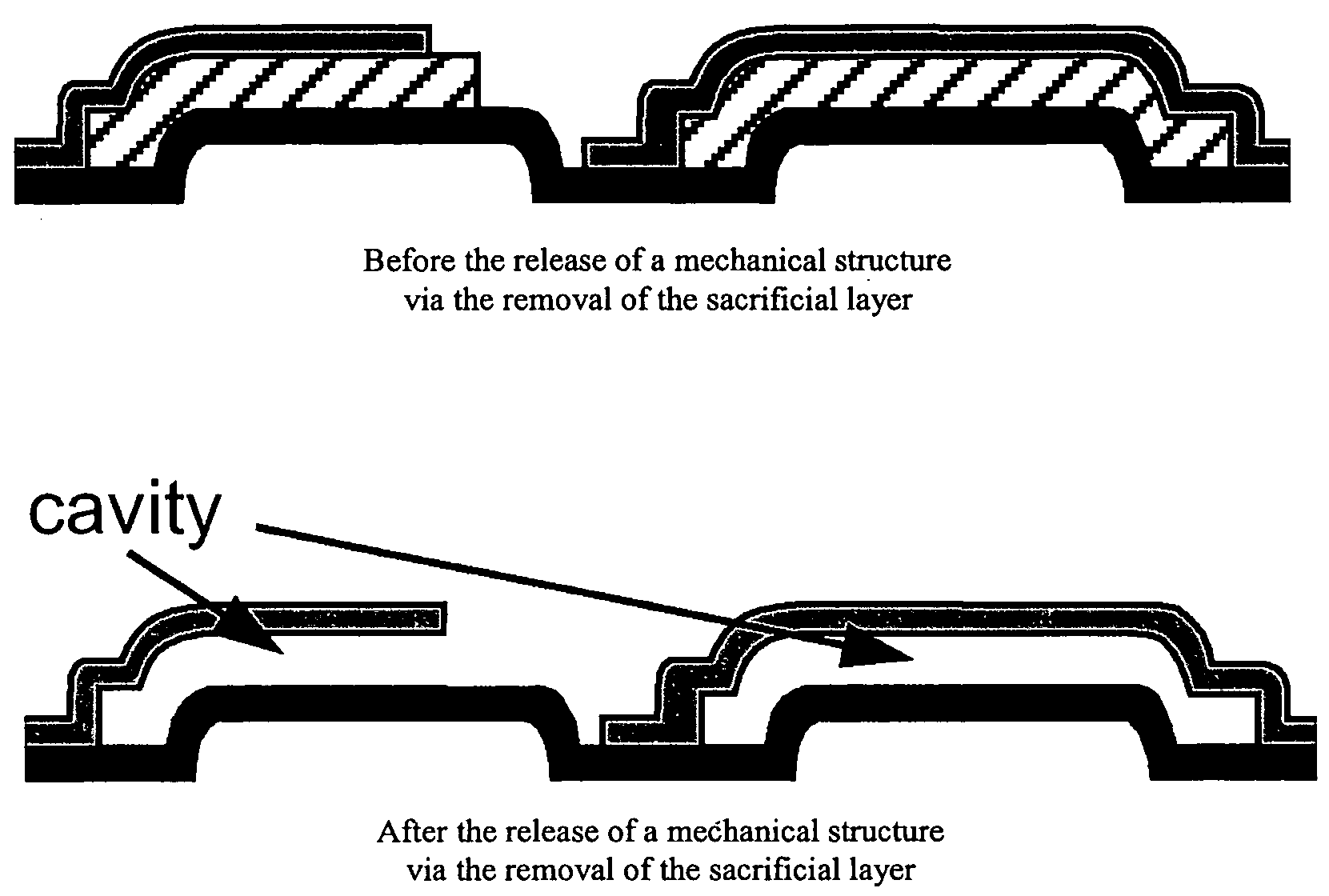
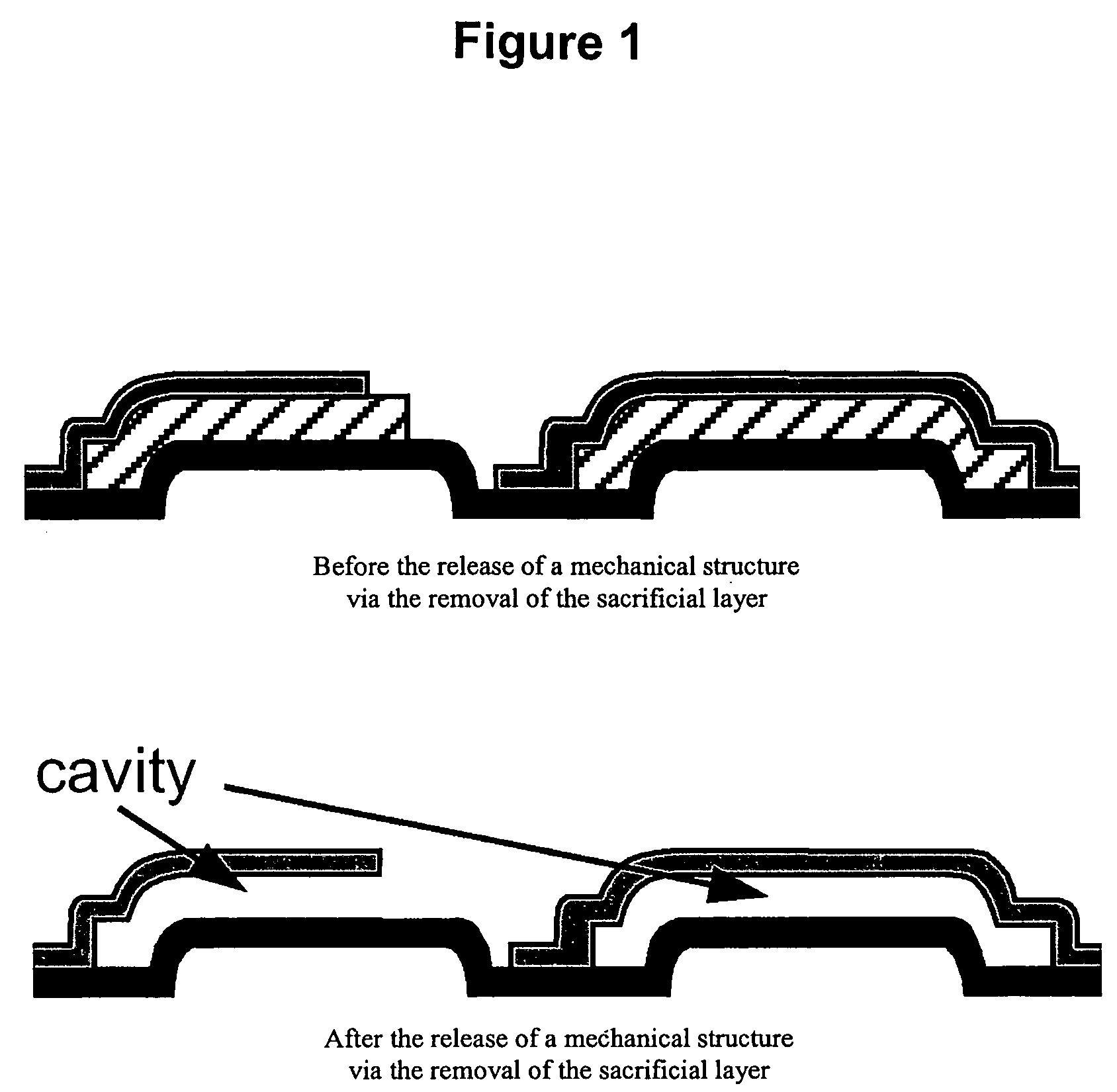
In the manufacture of MEMs device, the integration of very sensitive moving mechanical parts causes a very serious challenge because:These very sensitive mechanical parts are typically made of silicon (polysilicon or silicon-
germanium);The sacrificial material underlying these mechanical parts to be released is typically
silicon oxide;The etch-stop layer underlying this silicon
oxide sacrificial layer is typically
silicon nitride or silicon (polysilicon or silicon-
germanium);The mechanical release of the mechanical parts requires the removal of the sacrificial material in liquid HF-based chemistries;The
surface tension of these liquid HF-based chemistries is high enough to cause
stiction of the released mechanical parts onto the underlayers of
silicon nitride;
Liquid HF chemistries are not suitable for
stiction-free releases of sensitive MEMS devices.
Unfortunately, vapor HF also attacks the underlying silicon
nitride, producing an undesirable fluorinated silicon
nitride compound with a
rough surface.
Unfortunately, the fluorinated compound present onto the MEMS devices prior to such an ex-situ
evaporation is indeed toxic and its manipulation involves the
exposure of operators to this toxic fluorinated silicon nitride compound and / or to toxic vapors of this fluorinated silicon nitride compound resulting from its
evaporation.
More, the fluorinated compound is indeed unstable in presence of moist air and result in non-evaporable residues that cannot be evaporated in the ex-situ vacuum oven
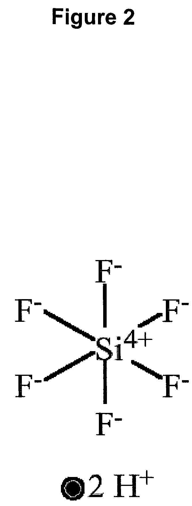
This means that improperly rinsed BHF released wafers will result in an undesirable
precipitation of
solid ammonium fluorosilicate, (NH4)2SiF6, crystals under the released mechanical parts.
Because
ammonium fluoride, NH4F, has a
melting point of 993° C., improperly rinsed mechanical parts released with BHF solutions and heated to high temperatures will also result in undesirable
refractory solid residues accumulating under the improperly rinsed mechanical parts.
Because advanced MEMS devices incorporating deep cavities and narrow access openings that cannot easily be rinsed, the use of BHF solutions in the manufacturing of such advanced MEMS devices gets much more complicated than the use of non-buffered HF solutions which do NOT result in the formation of such
solid by-products.
Unfortunately, the
surface tension of liquid 49 wt % HF solution causes a very undesirable
stiction effect on more flexible and more fragile mechanical parts than such rigid silicon blocks. FIG. 4 shows various 3D interferometric images of such an undesirable stiction effect on long and fragile cantilevers.
Such small differences of detachment length, Ld, of sensitive mechanical parts using smaller
surface tension drying liquids do not fulfill the requirements for most advanced MEMS devices integrating a large number of sensitive mechanical parts and does not safely prevent the stiction issues associated with such type of devices.
This supercritical CO2
drying technique is not that well suited for
mass production because the
high pressure of about 1200 psi (required to dry the released structures by passing from the
liquid phase to the
gas phase through the supercritical region and above the supercritical point of 31.1° C. and 1073 psi) imposes the use of bulky and thick walls mechanical chambers to manually load and dry, one-by-one, the
solvent-soaking substrates integrating advanced MEMS devices having their sensitive mechanical parts already released and yet dripping
solvent.
The above-mentioned release techniques involving liquid HF suffer from either stiction complications or lack of
automation, thus limiting the
mass production of advanced MEMS devices integrating sensitive mechanical parts.
Over these very serious problems, liquid-based HF solutions also suffer from
metal incompatibility issues.
These incompatibility issues are due to the fact that advanced MEMS devices typically integrate digital and / or analog
CMOS control logic and / or
high voltage CMOS drivers capable of performing actuation functions.
Unfortunately almost all
CMOS interconnect materials, namely aluminum alloys (such as aluminum-silicon, aluminum-
copper or aluminum-silicon-
copper alloys),
titanium (and
titanium compounds such as
titanium nitride) and
copper are rapidly attacked by these liquid-based HF solutions.
This clearly limits the use of liquid-based HF solutions for the
mass production of advanced MEMS devices integrating digital and / or analog CMOS
control logic and / or
high voltage CMOS drivers capable of performing actuation functions.

