Real-time implementation of field programmable gate arrays (FPGA) design in hyperspectral imaging

a hyperspectral imaging and field programmable gate array technology, applied in image enhancement, optical radiation measurement, instruments, etc., can solve the problems of reducing the payload of aircraft and satellites, limiting the applicability of real-time processing problems, and largely absent science data processing on board remote sensing missions

Inactive Publication Date: 2008-04-29
UNIV OF MARYLAND BALTIMORE COUNTY
View PDF4 Cites 9 Cited by
  • Summary
  • Abstract
  • Description
  • Claims
  • Application Information

AI Technical Summary

Benefits of technology

[0008]A further object of the present invention is to utilize the CORDIC to convert Givens rotations to a series of shifts-adds to use to decompose a matrix into triangular matrices that can be implemented in real time.

Problems solved by technology

Specifically, as spacecraft instruments generate data at an ever-increasing speed, on-board science data processing has been largely absent from remote sensing missions.
Furthermore, it can also reduce payload in aircrafts and satellites.
However, their applicability to real-time processing problem is generally restricted by very complex computational workloads.

Method used


Image

  • Real-time implementation of field programmable gate arrays (FPGA) design in hyperspectral imaging
  • Real-time implementation of field programmable gate arrays (FPGA) design in hyperspectral imaging
  • Real-time implementation of field programmable gate arrays (FPGA) design in hyperspectral imaging

Examples


first embodiment

[0046]In the invention for CEM implementation, Eq. (5) is decomposed into several components, each component implemented by a separated hardware module, whereby

[0047]w*=RL×L-1⁢ddT⁢RL×L-1⁢d=(XXT)-1⁢ddT⁡(XXT)-1⁢d=(Rtupper)-1⁡[(Rtupper)T]-1⁢ddT⁡(Rtupper)-1⁡[(Rtupper)T]-1⁢d.(11)

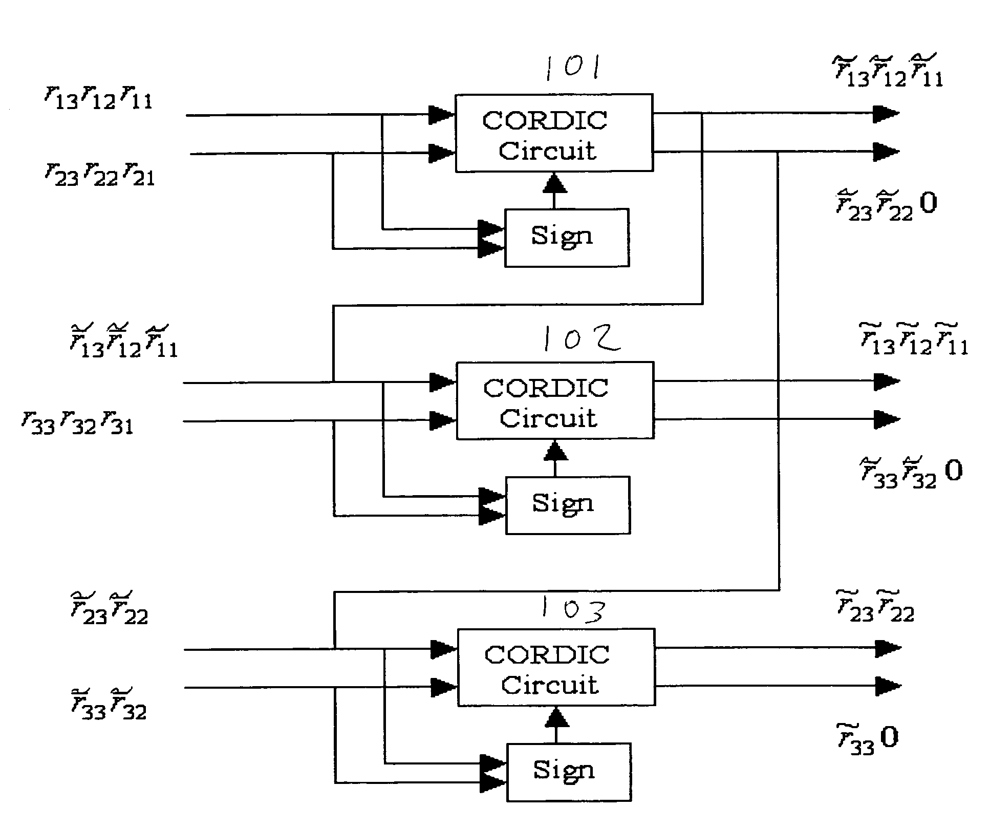
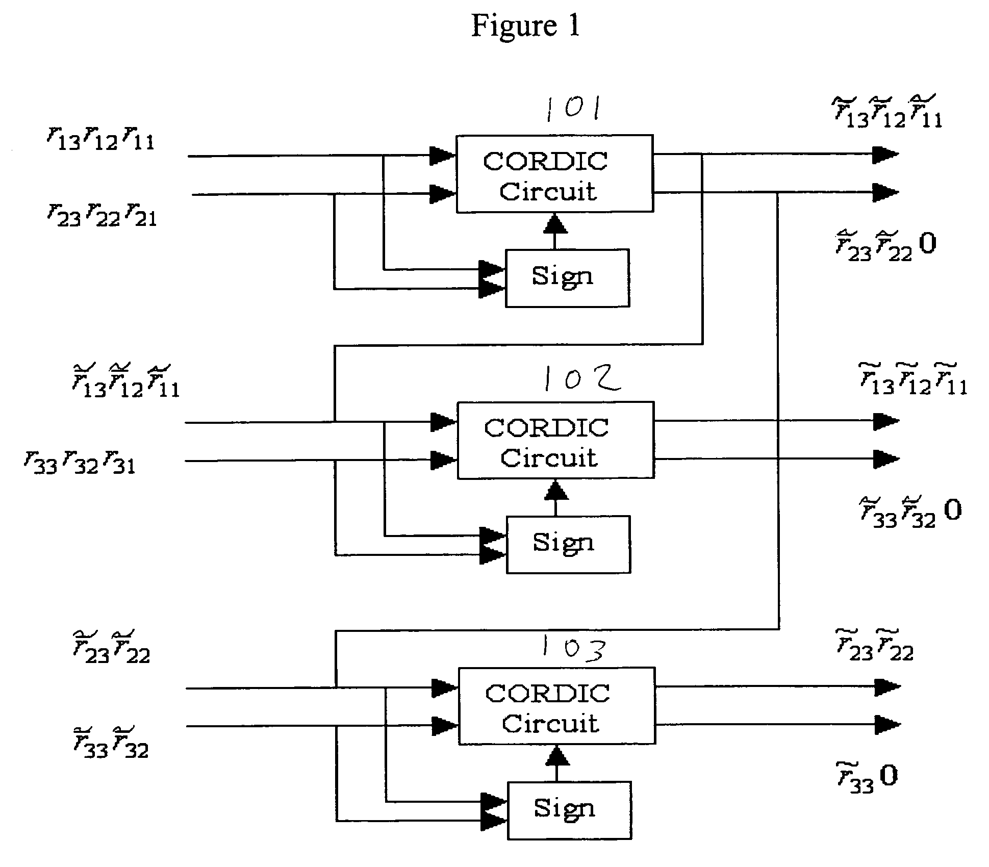
To implement Eq. (11), five modules are required:[0048]Module 1: Array of CORDIC circuits (101, 102, 103) shown in FIG. 1 where the pixel stream is fed into the module and the upper triangular matrix Rtupper is updated in real-time.[0049]Module 2: Apply backsubstitution to obtain the inverse of Rtupper invR.[0050]Module 3: Apply distributed arithmetic to calculate c=[(Rtupper)T]−1d=invRT*d.[0051]Module 4: Compute w=invRT*c.[0052]Module 5: The filter output energy can be obtained by applying a FIR filter to the current input pixel streams.

The detailed implementation for each of five modules is described as follows.

[0053]In Module 1, a set of CORDIC circuits (101, 102, 103) are applied to perform Givens rotation, a...

second embodiment

[0069]In the invention for CEM implementation, the correlation matrix is calculated before QR-decomposition shown in FIG. 6. Since dTRL×L−1 in Eq. (5) is a constant, RL×L−1d represents relative strength of detection power. Letting w=RL×L−1d, i.e. RL×Lw=d, where RL×L−1d can be implemented by a CORDIC module and followed by a backsubstitution module. As a result, four modules are required to implement this modified CEM detector:[0070]Module 1: Auto-correlator.[0071]Module 2: Apply CORDIC circuits to triangularize [R|d].[0072]Module 3: Apply backsubstitution to obtain w.[0073]Module 4: The filter output energy δCEM(r)=wTr can be obtained by applying a FIR filter to the current input pixel streams.

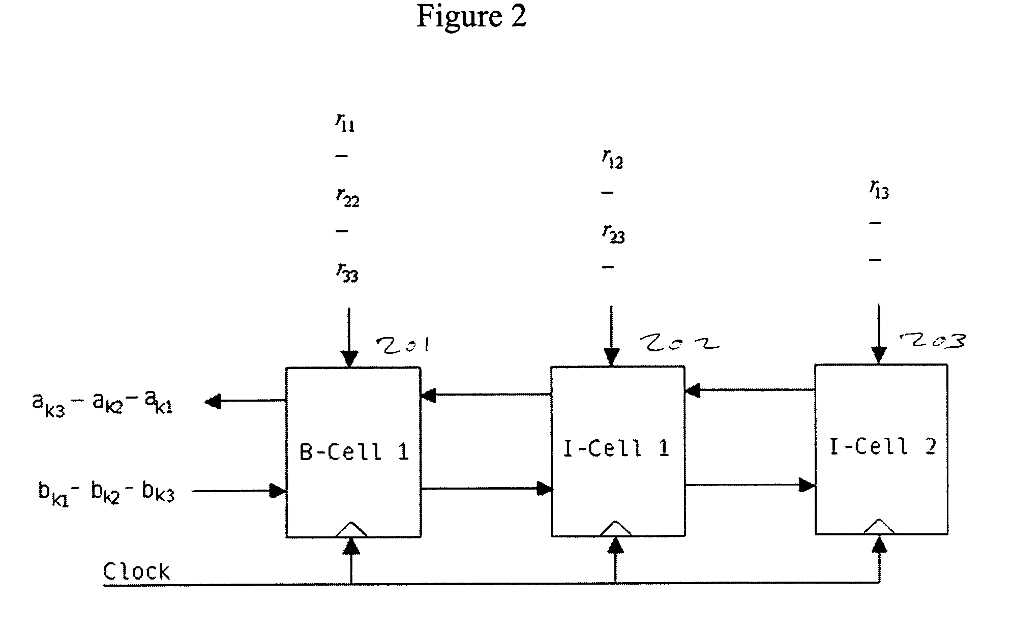
[0074]In Module 1, an auto-correlator generates the correlation matrix RL×L(i) with RL×L(i)=RL×L(i−1)+ririT and a pixel-by-pixel update process. In other words, the correlation matrix is updated every time a new pixel arrives. For illustrative purpose, let us assume L=3, then the new correlati...


PUM


Abstract

A Field Programmable Gate Arrays (FPGA) design uses a Coordinate Rotation DIgital Computer (CORDIC) algorithm that can convert a Givens rotation of a vector to a set of shift-add operations. The CORDIC algorithm can be easily implemented in hardware architecture, therefore in FPGA. Since the computation of the inverse of the data correlation matrix involves a series of Givens rotations, the utility of the CORDIC algorithm allows a causal Constrained Energy Minimization (CEM) to perform real-time processing in FPGA. An FPGA implementation of the causal CEM is described and its detailed architecture is also described.

Description

CROSS REFERENCE TO RELATED APPLICATIONS[0001]This application claims the benefit of U.S. Provisional Application No. 60 / 482,150, filed on Jun. 24, 2003 in the United States Patent and Trademark Office, the disclosure of which is hereby incorporated by reference.BACKGROUND OF THE INVENTION[0002]1. Field of the Invention[0003]The present invention relates to a Field Programmable Gate Arrays (FPGA) design and implementation, and more particularly to utilizing a Coordinate Rotation DIgital Computer (CORDIC) algorithm that allows a causal Constrained Energy Minimization (CEM) to perform real-time processing in FPGA for hyperspectral processing.[0004]2. Description of the Related Art[0005]The importance of real-time processing has been recently realized and recognized in many applications. In some applications, e.g. on-board spacecraft data processing system, it is very useful to have high levels of processing throughput. Specifically, as spacecraft instruments generate data at an ever-in...

Claims


Application Information

Patent Timeline
Patent Type & Authority Patents(United States)
IPC IPC(8): G06K9/00G06F7/38G06F7/544G06F17/11G06T5/00G06T5/20G06V20/13
CPCG06F7/5446G06F17/11G06K9/0063G06K9/00986G06T7/0081G06T2200/28G06T2207/10036G06T2207/20144G06T2207/30212G06T7/11G06T7/194G06V20/13G06V10/955
Inventor CHANG, CHEIN-IWANG, JIANWEI
Owner UNIV OF MARYLAND BALTIMORE COUNTY
Why Eureka
Try Eureka