Internal combustion engine and method of operating

a technology of internal combustion engine and combustion engine, which is applied in the direction of machines/engines, mechanical equipment, and non-fuel substance addition to fuel, etc., can solve the problems of inability to adopt the manufacture and use of internal combustion engines, inability to reduce and inability to achieve the effect of reducing the quantity of fuel required to operate the engin

Inactive Publication Date: 2008-05-06
HOLDEN RANDALL W
View PDF25 Cites 28 Cited by
  • Summary
  • Abstract
  • Description
  • Claims
  • Application Information

AI Technical Summary

Benefits of technology

[0005]According to the invention a quantity of water is injected into the combustion chamber after the fuel therein has been ignited. Upon the injection of a quantity of water into the combustion chamber of the cylinder the heat of combustion of the fuel will convert the water into superheated steam which will expand and generate a force which, in conjunction with the force generated by the burning of the fuel, will drive the piston through its power stroke. The force applied to the piston in response to the generation of the superheated steam may constitute the principal force applied to the piston during its power stroke, thereby minimizing the quantity of fuel required to operate the engine.

Problems solved by technology

Internal combustion engines currently in use which operate in response to the combustion of fuel in one or more cylinders are relatively inefficient inasmuch as the major portion of heat generated by the combustion of the fuel is released to atmosphere without otherwise being utilized.
The loss of such heat is undesirable for a number of reasons, not the least of which is the necessity of having to rely on the combustion of large quantities of fuel to ensure appropriate operation of the engine.
The prior art contains many proposals for improving engine efficiency and conservation of fuel, but a good many of such proposals have not been adopted in the manufacture and use of internal combustion engines.

Method used


Image

  • Internal combustion engine and method of operating
  • Internal combustion engine and method of operating
  • Internal combustion engine and method of operating

Examples


Embodiment Construction

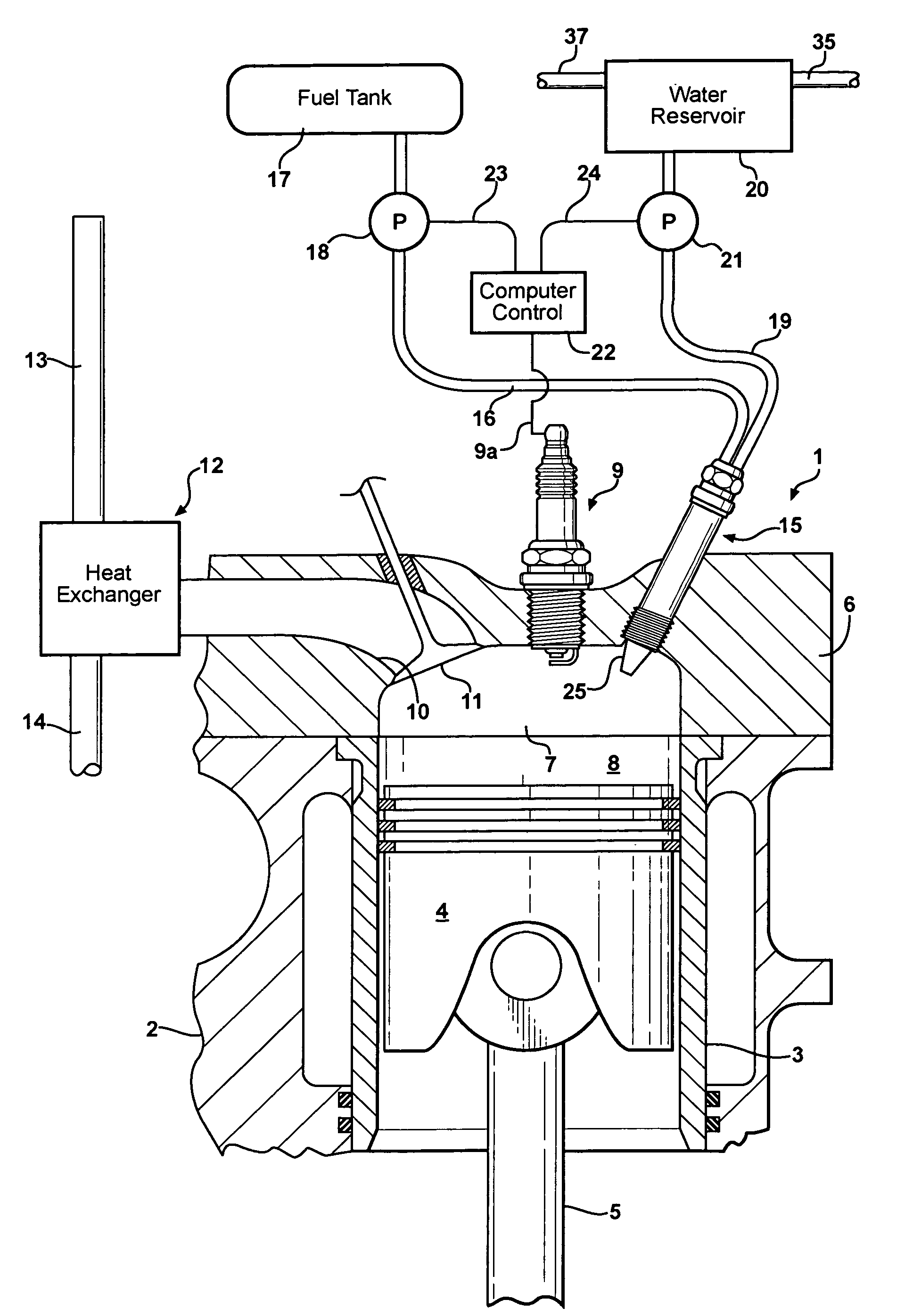
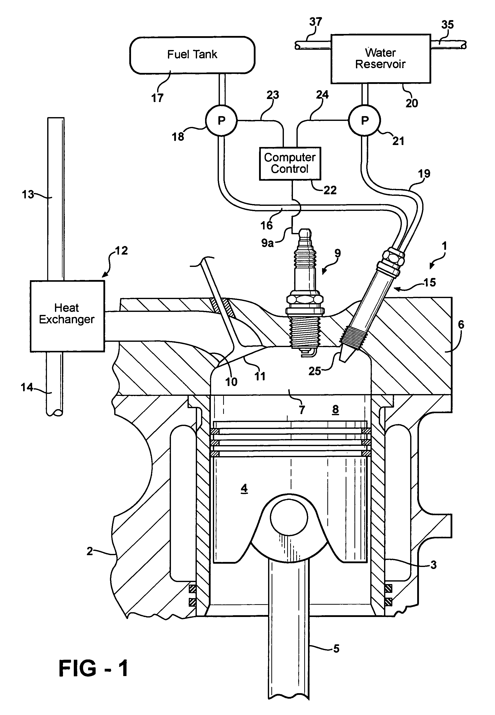
[0010]An internal combustion engine constructed in accordance with the invention is designated generally by the reference character 1 and includes an engine block 2 within which is a plurality of cylinders, one of which is shown at 3. Within the cylinder is a reciprocable piston 4 coupled to a piston rod 5 which is reciprocated by a rotary cam shaft (not shown) as is conventional. Atop the block 2 is a cylinder head 6 having a cavity 7 in communication with the cylinder 3, thereby forming with the upper end of the cylinder a combustion chamber 8. Mounted in the cylinder head 6 and extending into the combustion chamber is a conventional ignition or spark plug 9 coupled by wiring (not shown) to a conventional ignition system. An exhaust passage 10 communicates with the combustion chamber 8 and normally is closed by an exhaust valve 11 which periodically is actuated in a conventional manner to enable the contents of the combustion chamber to be exhausted from the latter following the p...


PUM


Abstract

An internal combustion engine having at least one cylinder within which is a reciprocable piston movable in a compression stroke followed by movement in a power stroke and wherein a combustible fuel mixture is injected into the combustion chamber, compressed, ignited, and burned to produce the power stroke of the piston. After the fuel has been ignited and during the compression of such mixture a quantity of water from a reservoir is injected into the combustion chamber and converted by the heat of combustion into superheated steam, thereby generating within the combustion chamber a force which assists in driving the piston through its power stroke. The products of combustion and steam are discharged from the cylinder following the power stroke and cooled in a heat exchanger in which the steam is condensed, following which the gases are exhausted and the condensate returned to the water reservoir.

Description

[0001]This invention relates to an internal combustion engine and a method of operating such engine in such manner as to minimize the fuel required for operation.BACKGROUND OF THE INVENTION[0002]Internal combustion engines currently in use which operate in response to the combustion of fuel in one or more cylinders are relatively inefficient inasmuch as the major portion of heat generated by the combustion of the fuel is released to atmosphere without otherwise being utilized. The loss of such heat is undesirable for a number of reasons, not the least of which is the necessity of having to rely on the combustion of large quantities of fuel to ensure appropriate operation of the engine. The prior art contains many proposals for improving engine efficiency and conservation of fuel, but a good many of such proposals have not been adopted in the manufacture and use of internal combustion engines.[0003]A principal object of this invention is to provide an internal combustion engine and m...

Claims


Application Information

Patent Timeline
Patent Type & Authority Patents(United States)
IPC IPC(8): F02B47/02
CPCF02B47/02F02M25/0222F02M25/03Y02T10/121Y02T10/12
Inventor HOLDEN, RANDALL W.
Owner HOLDEN RANDALL W
Why Eureka
Try Eureka