Envelope, envelope manufacturing method, image display device, and television display device
- Summary
- Abstract
- Description
- Claims
- Application Information
AI Technical Summary
Benefits of technology
Problems solved by technology
Method used
Image

Examples
embodiment 1
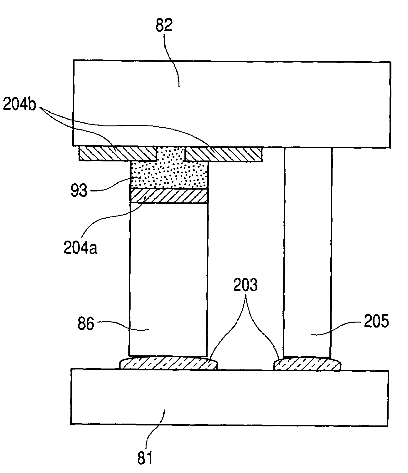
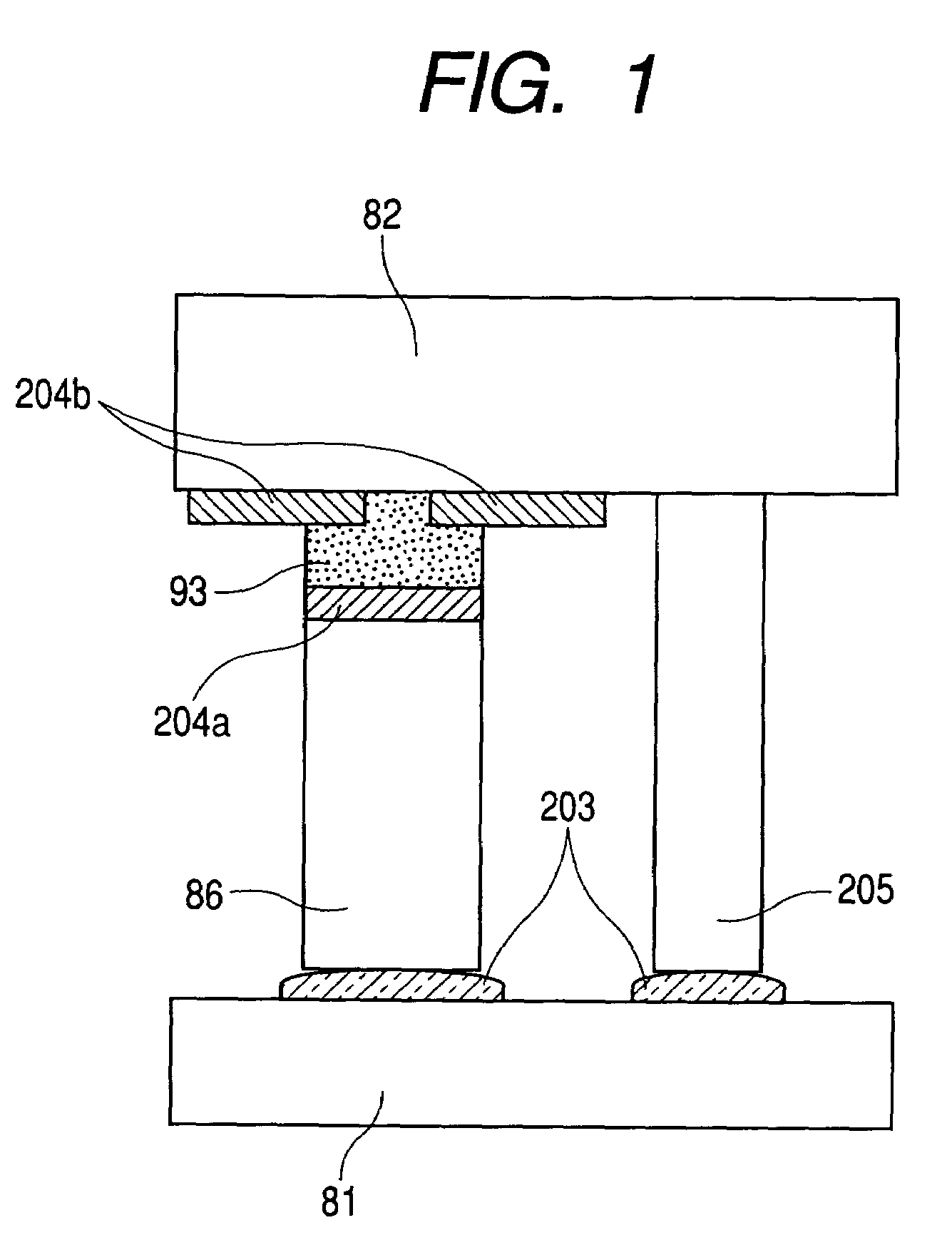
[0040]FIG. 12 is a schematic diagram which outlines a structural example of an envelope. FIG. 1 is a schematic diagram which outlines a sectional structure of a peripheral portion of an envelope according to Embodiment 1. In a peripheral portion of an envelope 90, a face plate 82 which is a first substrate and a supporting frame 86 are bonded to each other through an In film 93 which is a low melting point metal. Reference numeral 80 denotes an electron source with a large number of electron-emitting devices arranged thereon. Denoted by 81 is a glass substrate having the electron source substrate 80 on one side. The substrate 81 is called a rear plate which is a second substrate. The face plate 82 is composed of a glass substrate 83 and a fluorescent film and metal back which line the inner surface of the glass substrate 83. A supporter called a spacer 205 is set between the face plate 82 and the rear plate 81 to give the envelope 90 enough strength against atmospheric pressure even...
embodiment 2
[0136]FIG. 18 outlines a sectional structure of a bonding portion on the perimeter of an envelope according to another embodiment of the present invention. This embodiment is identical with Embodiment 1 except that the first region for ensuring the airtightness, namely, the underlayer 204b, of the face plate 82 which is the first substrate is formed only on the image display region side while the second region for ensuring the adhesion is formed only on the outside of the first region.
embodiment 3
[0137]FIG. 19 outlines a sectional structure of a bonding portion on the perimeter of an envelope according to still another embodiment of the present invention.
[0138]In this embodiment, an In film is also used to bond the supporting frame 86 and the rear plate 81, which is the second substrate. On the side of the supporting frame 86 that faces the rear plate 81, the underlayer 204b is formed as the first region for ensuring the airtightness only on the image display region side while the second region for ensuring the adhesion is formed only on the outside of the first region. The rest of this embodiment is similar to Embodiment 2. Using In to bond the supporting frame 86 and the rear plate 81 to each other makes a low temperature bonding process possible.
[0139]The face plate serves as the first substrate and the rear plate serves as the second substrate in the above embodiments. Specifically, Embodiment 1 describes a structure in which the face plate serving as the first substrate...
PUM
 Abstract
Description
Claims
Application Information