Anisotropic texture filtering with a modified number of texture samples

Active Publication Date: 2008-05-13
NVIDIA CORP
View PDF13 Cites 8 Cited by
  • Summary
  • Abstract
  • Description
  • Claims
  • Application Information

AI Technical Summary

Benefits of technology

[0012]The current invention involves new systems and methods for determining the number and spacing of texture samples to use to produce an anisotropically filtered texture mapped pixel. Reducing the number of texture samples used to produce an anisotropically filtered texture mapped pixel may improve texture mapping performance since fewer texels will be read from a texture map and processed. The number of texture samples is reduced based on the mip map level weight. The number of texture samples may be further modified using specific parameters for the coarse and / or fine mip map levels. The spacing between the texture samples along the major axis of anisotropy may also be modified.
[0013]Various embodiments of a method of the invention for modifying a number of texture samples used to produce an anisotropically filtered texture value for a footprint include determining a mip map level weight using a length of a minor axis of the footprint, determining a spread between each of the number of texture samples for a level of detail of a mip mapped texture based on the mip map level weight, and increasing or decreasing the number of texture samples taken from the mip map level as a function of the spread to produce a modified number of texture samples.

Problems solved by technology

Therefore, portions of the footprint are not sampled, resulting in visual artifacts caused by undersampling.
When isotropic filtering is used in such situations, a circle is not a good approximation of an ellipse.
If the circle is too small (diameter close to the minor axis), the filter is too sharp, too few texels are averaged, and aliasing results.
If the circle is too large (diameter close to the major axis), the filter is too broad, too many texels are averaged, and blurring results.
Therefore the coarse LOD mip map is oversampled, possibly introducing visual artifacts and requiring more computations and texel reads than if the spacing were one texel apart.

Method used


Image

  • Anisotropic texture filtering with a modified number of texture samples
  • Anisotropic texture filtering with a modified number of texture samples
  • Anisotropic texture filtering with a modified number of texture samples

Examples


Embodiment Construction

[0038]In the following description, numerous specific details are set forth to provide a more thorough understanding of the present invention. However, it will be apparent to one of skill in the art that the present invention may be practiced without one or more of these specific details. In other instances, well-known features have not been described in order to avoid obscuring the present invention.

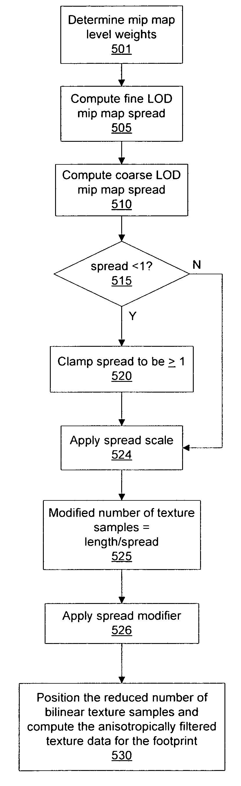
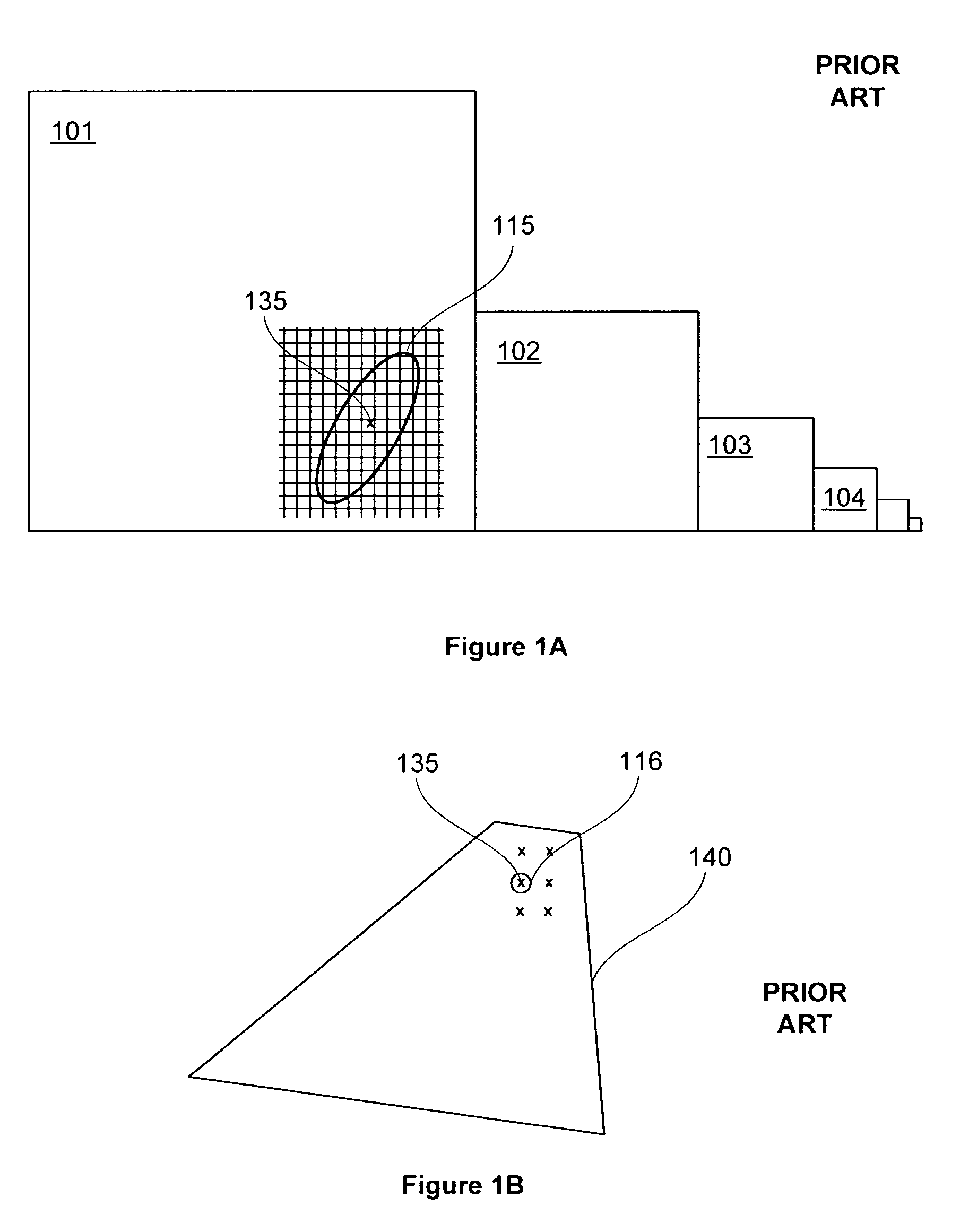
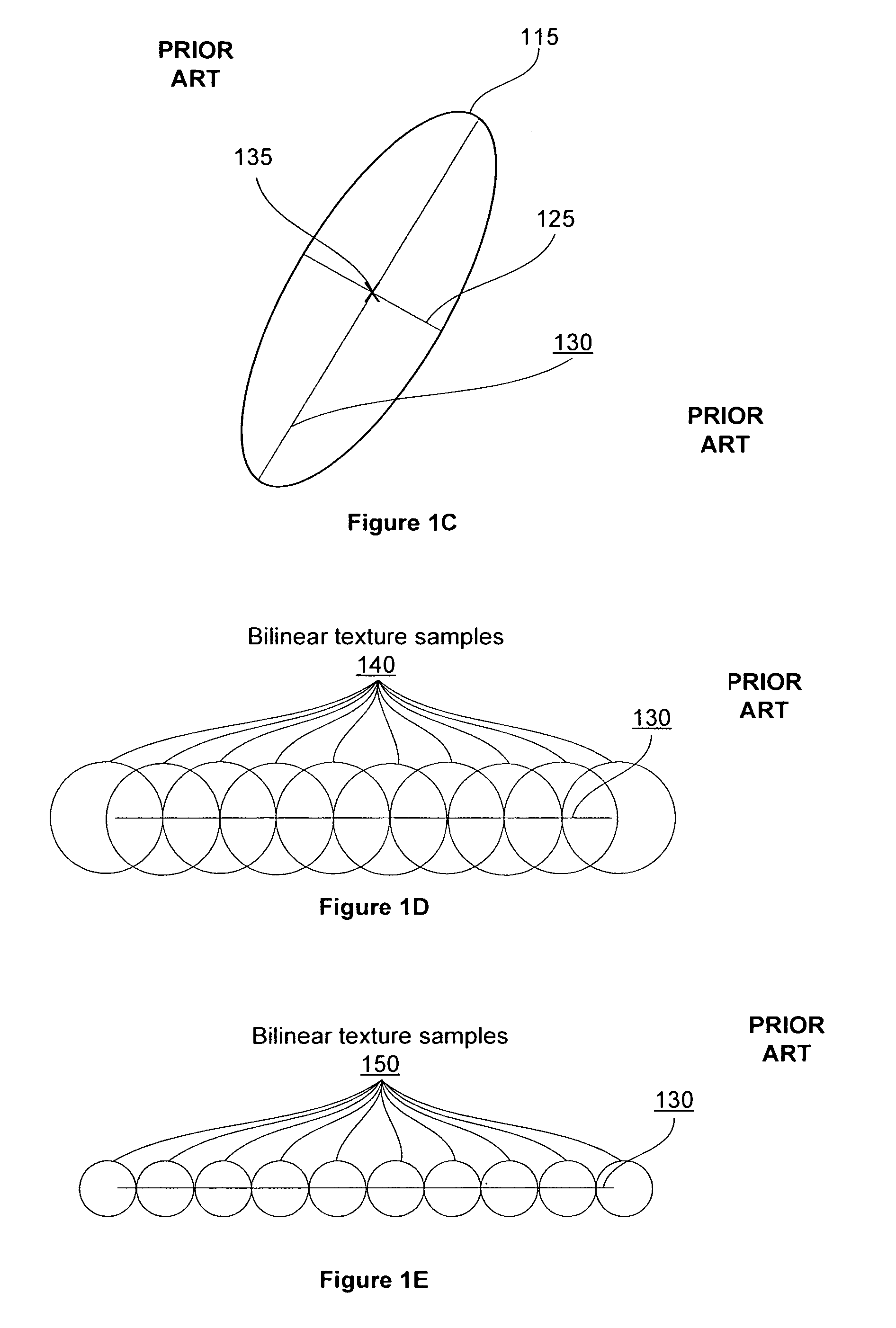
[0039]The major and minor axes of anisotropy define a footprint that represents the projection of the pixel onto the texture map. Texture samples are positioned along the axis of anisotropy (the major axis) to approximate the footprint. The number of texture samples determines the number of texture samples which are read from an LOD of a mip mapped texture map and filtered to produce an anisotropically filtered texture value. When the LOD is not an integer value, texture samples are used from two different LOD mip maps and the number of texture samples read from at least one of the LOD ...


PUM


Abstract

Systems and methods for modifying the number of texture samples used to produce an anisotropically filtered texture mapped pixel may improve texture mapping performance. When the number of texture samples is reduced, fewer texels are read and fewer filtering computations are needed to produce a texture value for an anisotropic footprint. The number of texture samples is reduced based on the mip map level weight. The number of texture samples may also be modified using specific parameters for the coarse and / or fine mip map levels. The spacing between the texture samples along the major axis of anisotropy may be modified to improve image quality or texture cache performance.

Description

BACKGROUND OF THE INVENTION[0001]1. Field of the Invention[0002]Embodiments of the present invention generally relate to computer graphics, and more particularly to anisotropic filtering of texture data.[0003]2. Description of the Related Art[0004]Conventional graphics processors are exemplified by systems and methods developed to read and filter texture map samples. To simplify the texture map filtering performed within a graphics processor, a texture is prefiltered and various resolutions forming an image pyramid or “mipmap” are stored. FIG. 1A is a conceptual diagram of prior art showing the levels of a mipmapped texture including the finest level, level 101, and successively lower resolution levels, 102, 103, and 104. In some systems, mipmap levels are numbered such that level 0 is the highest resolution, “base” level, and level k is half the size in each dimension of level k−1, for all k up to the apex of the pyramid.[0005]The region in texture space corresponding to a pixel is...

Claims


Application Information

Patent Timeline
IPC IPC(8): G09G5/00
CPCG06T15/04G06T11/40G06F3/14G06T2210/36
Inventor TOKSVIG, MICHAEL J. M.NEWHALL, JR., WILLIAM P.
Owner NVIDIA CORP
Why Eureka
Try Eureka