
Power conditioning system for energy sources

a technology of power conditioning system and energy source, applied in the direction of electric variable regulation, process and machine control, instruments, etc., can solve the problems of increasing thermal stress on the power stage components, reducing the maximum power output available from the fc stack, and degrading the reliability of the overall p

Inactive Publication Date: 2008-05-13
THE BOARD OF TRUSTEES OF THE UNIV OF ILLINOIS
View PDF8 Cites 62 Cited by
  • Summary
  • Abstract
  • Description
  • Claims
  • Application Information

AI Technical Summary

Problems solved by technology

However, at higher power it suffers from problems due to transformer flux imbalance and core-saturation.
However, for high-voltage applications, the voltage stress on the switches increases significantly, thereby degrading the reliability of the overall PCS.
It is known that a large ripple current will reduce the maximum power output available from the FC stack, but apart from this little is known about the dynamic electrical performance, particularly with regard to long-term effects.
Apart from the direct effect on the fuel cell durability, the harmonics have the effect of increasing the power-conditioner copper, iron and dielectric losses and thus increasing the thermal stress on the power stage components.
Power derating of the individual components and over sizing is a preventive measure which results in compromise in power density and increased costs.

Method used


Image

  • Power conditioning system for energy sources
  • Power conditioning system for energy sources
  • Power conditioning system for energy sources

Examples


Embodiment Construction

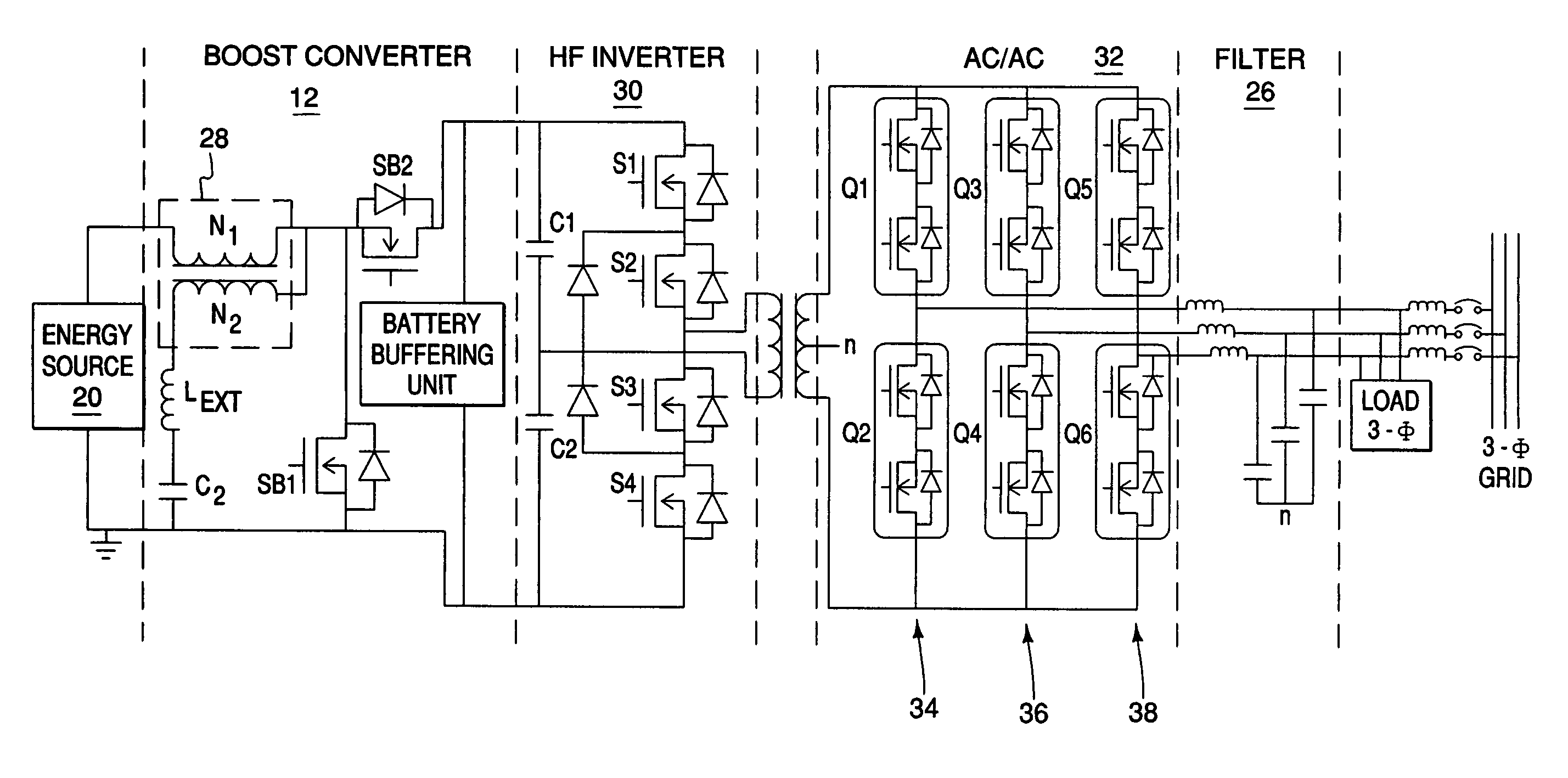
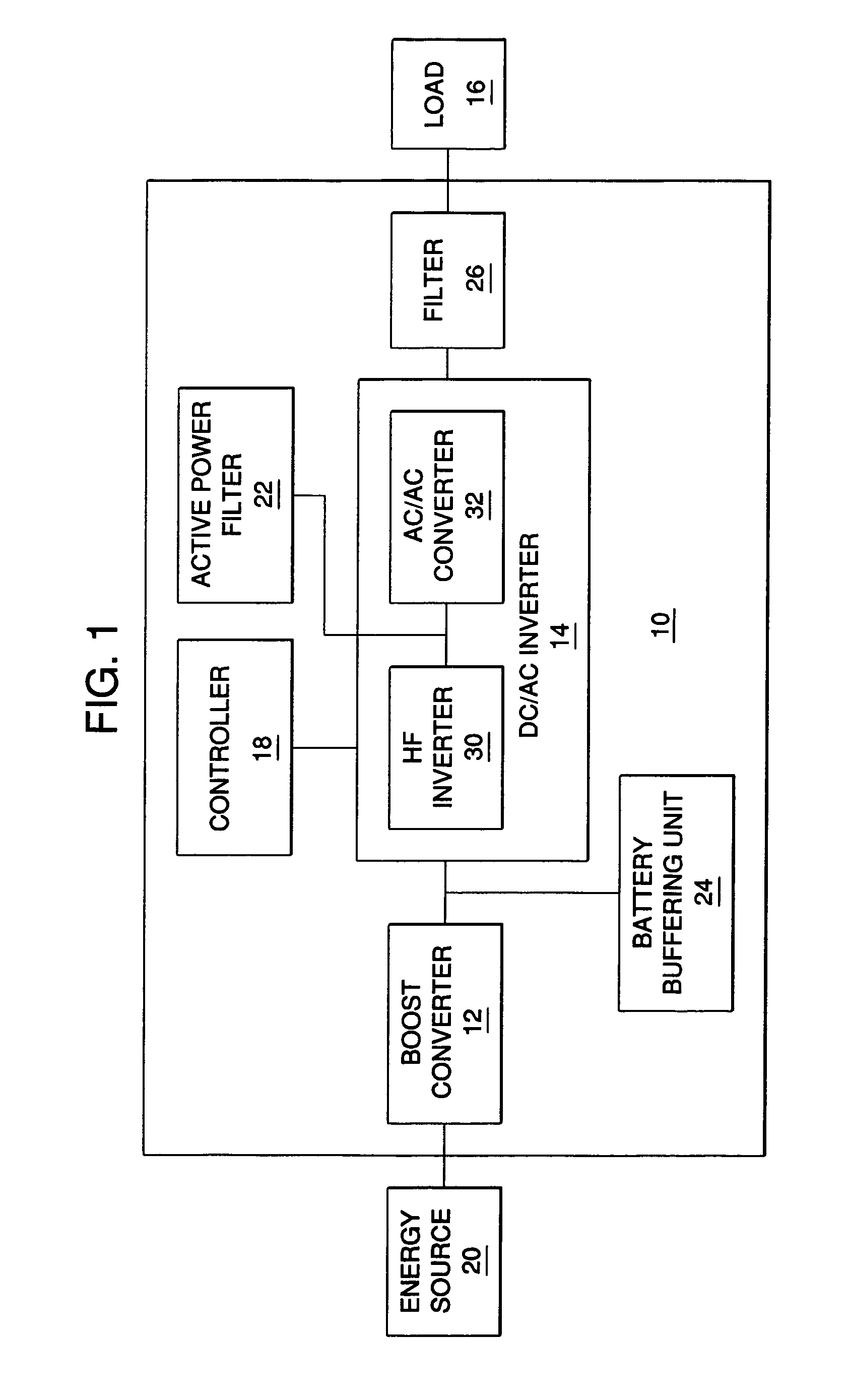
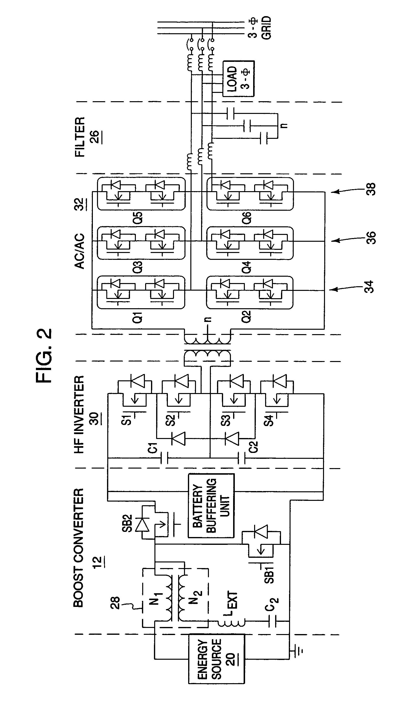
[0026]Turning now to FIG. 1, a power conditioning systems (PCS) 10 in accordance with one embodiment of the present invention includes a boost converter 12 for stepping up the input DC voltage to a HVDC, followed by a DC / AC inverter 14, the output of which is connected to a load 16 which may be a stand-alone load or a utility grid, for example. A controller 18 controls the operation of the DC / AC inverter 14. The boost converter 12 generates a high voltage DC (e.g., >350V) at its output and the DC / AC inverter 14 generates a single, two or three phase AC voltage at its output. The input DC voltage is supplied by an alternative-energy source 20 such as, for example, a fuel cell (FC) source. The PCS 10 of the present invention also includes an active power filter 22 for minimizing the low frequency ripple current harmonics in the output current of the energy source 20, a battery buffering unit 24 for providing the excess energy during a load transient, and a low pass filter 26 connected...


PUM


Abstract

Apparatus for conditioning power generated by an energy source includes an inverter for converting a DC input voltage from the energy source to a square wave AC output voltage, and a converter for converting the AC output voltage from the inverter to a sine wave AC output voltage.

Description

RELATED APPLICATION REFERENCE AND PRIORITY CLAIM[0001]This application is a CIP of U.S. patent application No. 10 / 938,469 filed Sep. 10, 2004, which claims priority of U.S. Provisional Application No. 60 / 501,955, filed Sep. 11, 2003, under 35 U.S.C. § 119.STATEMENT OF GOVERNMENT INTEREST[0002]The invention was made with Government assistance under Department of Energy, Grant No. DE-FC2602NT41574. The Government has certain rights in this invention.FIELD OF THE INVENTION[0003]A field of the invention is in power conditioning systems, and in particular, but not limited to, a power conditioning system for alternative-energy sources such as fuel cell and photovoltaic.BACKGROUND OF THE INVENTION[0004]Hydrogen fuel cell (FC) energy and photovoltaic energy are examples of the front-runners among alternate-energy solutions to address and alleviate the imminent and critical problems of existing fossil-fuel-energy systems: environmental pollution due to high emission level and rapid depletion...

Claims


Application Information

Patent Timeline
Patent Type & Authority Patents(United States)
IPC IPC(8): H02M3/335H02J1/02H02J3/38H02M7/48H02M7/5387H02M7/5395
CPCH02J3/387H02M7/4807H02M7/53875H02M7/5395H02J2001/004H02M7/487H02J2300/30H02J3/381H02M1/0095H02M7/4837H02J2300/24Y02E10/56
Inventor MAZUMDER, SUDIP K.BURRA, RAJNI K.ACHARYA, KAUSTUVA
Owner THE BOARD OF TRUSTEES OF THE UNIV OF ILLINOIS
Learn More