Method for manufacturing a fluid pressure measurement unit and a component for being used in a fluid pressure measurement unit

a technology of fluid pressure measurement and manufacturing method, which is applied in the direction of sensors, medical devices, catheters, etc., can solve the problems of limiting the selection of material candidates with respect to other desired material characteristics, cost- and time-consuming, and time-consuming in the manufacturing process of the transistor type illustrated in fig. 4 to achieve a less cost- and time-consuming way of manufacturing

Inactive Publication Date: 2008-05-20
SMITHS MEDICAL DEUTLAND
View PDF6 Cites 20 Cited by
  • Summary
  • Abstract
  • Description
  • Claims
  • Application Information

AI Technical Summary

Benefits of technology

[0018]It is thus the object of the present invention to provide a component for inserting a fluid pressure measurement unit and a method for manufacturing a component of a fluid pressure measurement unit which enable a less cost- and time-consuming way of manufacturing, respectively.

Problems solved by technology

Due to the high number of individual parts, the manufacturing process for the type of transistor illustrated in FIG. 4 is cost- and time-consuming.
Due to the high temperatures occurring during soldering, the contact carrier 414 has to be manufactured from an especially temperature- and form-stable material, which is cost- and time-consuming and also limits the selection of material candidates with respect to other desired material characteristics.
This could lead to an electrical connection between the contacts and to a drift of the pressure measurement signal.
Thus, it is required to perform a special examination of the tightness between the top housing part 418 and the bottom housing part 402, which is time-consuming and in particular in mass production of such transducers also costly.
This filling in may, however, due to reasons of manufacturing technology, only take place by means of a cost- and time-consuming method using a syringe through the flow channel 120.

Method used


Image

  • Method for manufacturing a fluid pressure measurement unit and a component for being used in a fluid pressure measurement unit
  • Method for manufacturing a fluid pressure measurement unit and a component for being used in a fluid pressure measurement unit
  • Method for manufacturing a fluid pressure measurement unit and a component for being used in a fluid pressure measurement unit

Examples


Embodiment Construction

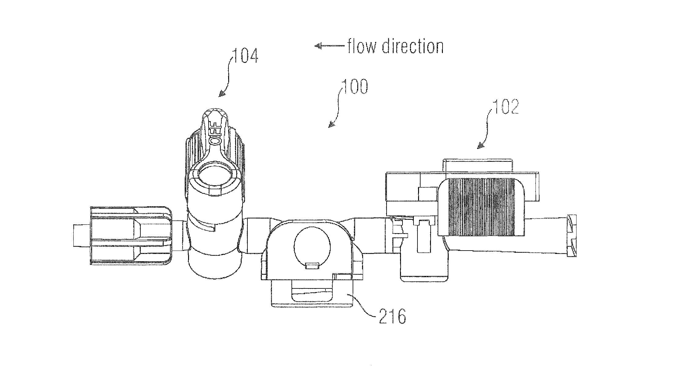
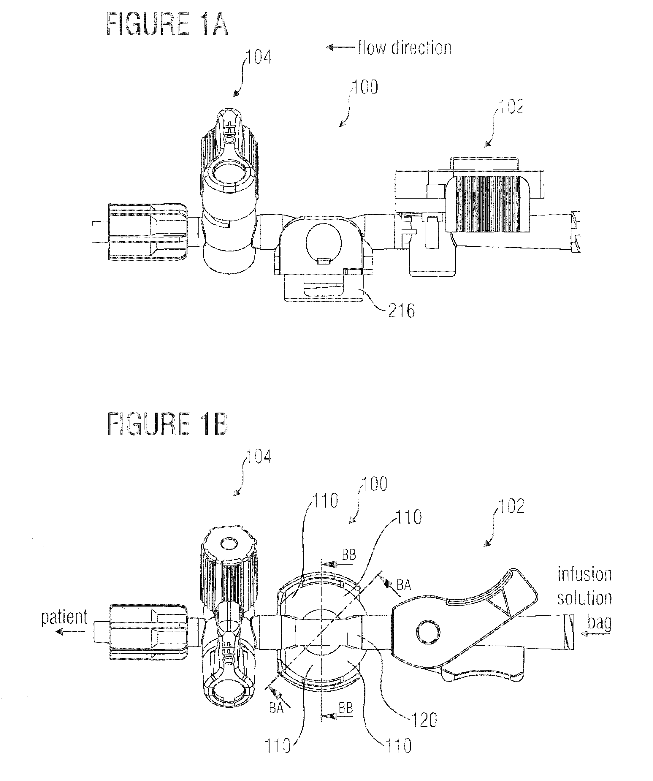
[0055]FIG. 1A shows a section from a pressure measurement system comprising a transducer or pressure gauge 100. Here, the pressure gauge 100 may be integrated into the pressure measurement system such that it is arranged in the flow direction of the infusion solution behind a rinsing system (first tap) 102 and before a second tap 104. The rinsing system 102 may be arranged towards an infusion solution reservoir, while the second tap 104 is, for example, connected between the transducer 100 and the patient. By the rinsing system 102 it may be guaranteed, that the transducer is protected from pressure variations, caused by the infusion system, and that a desired flow rate is guaranteed, while the second tap 104 may be closed when actions, like, for example, taking a blood sample, are being performed at the patient. Additionally, the second tap may be used for “zeroing” the pressure sensor against atmospheric pressure.

[0056]Also other embodiments with taps (102, 104) at both ends or co...


PUM

PropertyMeasurementUnit
flow rateaaaaaaaaaa
pressureaaaaaaaaaa
areaaaaaaaaaaa

Abstract

A fluid pressure measurement unit is manufactured by steps of providing a measurement element with a measurement chip arranged on a first chip carrier side and a plurality of socket-shaped terminal contacts for contacting contact terminals of the measurement chip, the socket-shaped terminal contacts protruding from a second chip carrier side opposite from the chip carrier first side; providing a housing element comprising a plurality of receiving holes in a housing element first side which are implemented to receive the socket-shaped terminal contacts when combining the housing element with the measurement element, wherein the receiving holes extend from the housing element first side to a housing element second side opposite from the housing element first side; and combining the measurement element and the housing element, wherein the second chip carrier side is opposite from the housing element first side and the socket-shaped terminal contacts are arranged in the receiving holes.

Description

CROSS-REFERENCE TO RELATED APPLICATION[0001]This application claims priority from German Patent Application No. 102006008752.6, which was filed on Feb. 24, 2006, and is incorporated herein by reference in its entirety.BACKGROUND OF THE INVENTION[0002]1. Field of the Invention[0003]The present invention relates to the technical field of fluid pressure measurement and in particular to the manufacturing of a component for a fluid pressure measurement unit, like, e.g., those used for blood pressure measurement by pressure transmission by means of a liquid column, like the liquid in a pressure measurement tube or a pressure measurement line, respectively.[0004]2. Description of Related Art[0005]In order to cause the least possible effort in hospitals or clinics in the care of patients, there is an increasing interest in combining different measurement and diagnosis systems with each other, in order to hereby on the one hand deal with an excessive fear of patients with regard to an excess...

Claims


Application Information

Patent Timeline
Patent Type & Authority Patents(United States)
IPC IPC(8): A61B5/02
CPCA61M5/16854G01L19/0023A61M39/22A61M2205/3344Y10T29/49144A61M2230/30Y10T29/49171Y10T29/49146
Inventor WEBER, JOERGBECK, BERND
Owner SMITHS MEDICAL DEUTLAND
Why Eureka
Try Eureka