Method of and device for lubricating rolling bearings
a technology of rolling bearings and lubricating pads, which is applied in the direction of positive displacement liquid engines, lubricant transfer, piston pumps, etc., can solve the problems of lowering the ability of lubricant oil to form an oil film, difficult for lubricant oil to be lubricated, and increasing the temperature of the bearing body
- Summary
- Abstract
- Description
- Claims
- Application Information
AI Technical Summary
Benefits of technology
Problems solved by technology
Method used
Image
Examples
first embodiment
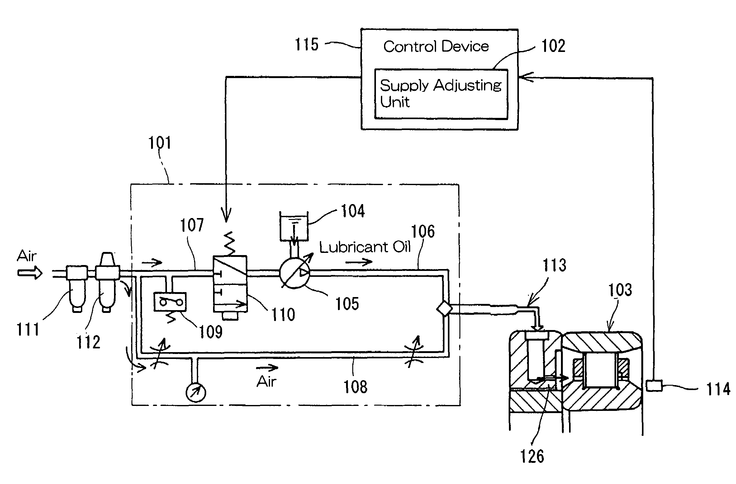
[0096]Hereinafter, the lubricating method for the rolling bearing assembly according to the present invention, which utilizes the lubricating device of the structure described above, will be described. During the operation of the rolling bearing assembly 103, the rotational speed of the inner race of the rolling bearing assembly 103 is monitored by the rotational speed detecting unit 114. The information signal indicative of the rotational speed detected by the rotational speed detecting unit 114 is compared by the supply adjusting unit 102 with a predetermined speed (r.p.m) dividing the rotational speed regions, and the supply adjusting unit 102 subsequently outputs a signal indicative of the preset supply amount for the corresponding speed region. This signal is used for causing the solenoid valve 110 to be brought in an opened position and the interval of this signal represents the interval of supply of the air / oil mixture from the nozzle 106.
[0097]The supply adjusting unit 102 d...
third embodiment
[0153]FIGS. 16 and 17 illustrate air / oil lubricating structures for the rolling bearing assembly according to fifth and sixth preferred embodiments of the present invention, respectively. Those embodiments are substantially similar to the previously described third embodiment of FIG. 14, except that in those embodiments of FIGS. 16 and 17, the retainers 5A (FIG. 14) employed in the cylindrical roller bearing 1A are replaced with a comb-shaped retainer 5B. While the retainer 5A employed in the example shown in FIG. 14 is of a cage type designed to have pockets each embracing the corresponding rolling element 4A in the form of a cylindrical roller, the comb-shaped retainer 5B has pockets each designed to encompass the corresponding rolling element 4A in the form of a cylindrical roller from three directions while opening in one direction. Because of this, a generally ring-shaped guide side plate19 adjoining an end face of a cylindrical portion of the comb-shaped retainer 5B is fixed t...
second embodiment
[0156]Other structural features of each of the embodiments shown in and described with particular reference to FIGS. 16 and 17, respectively, are substantially similar to those in the second embodiment shown in and described with particular reference to FIG. 9.
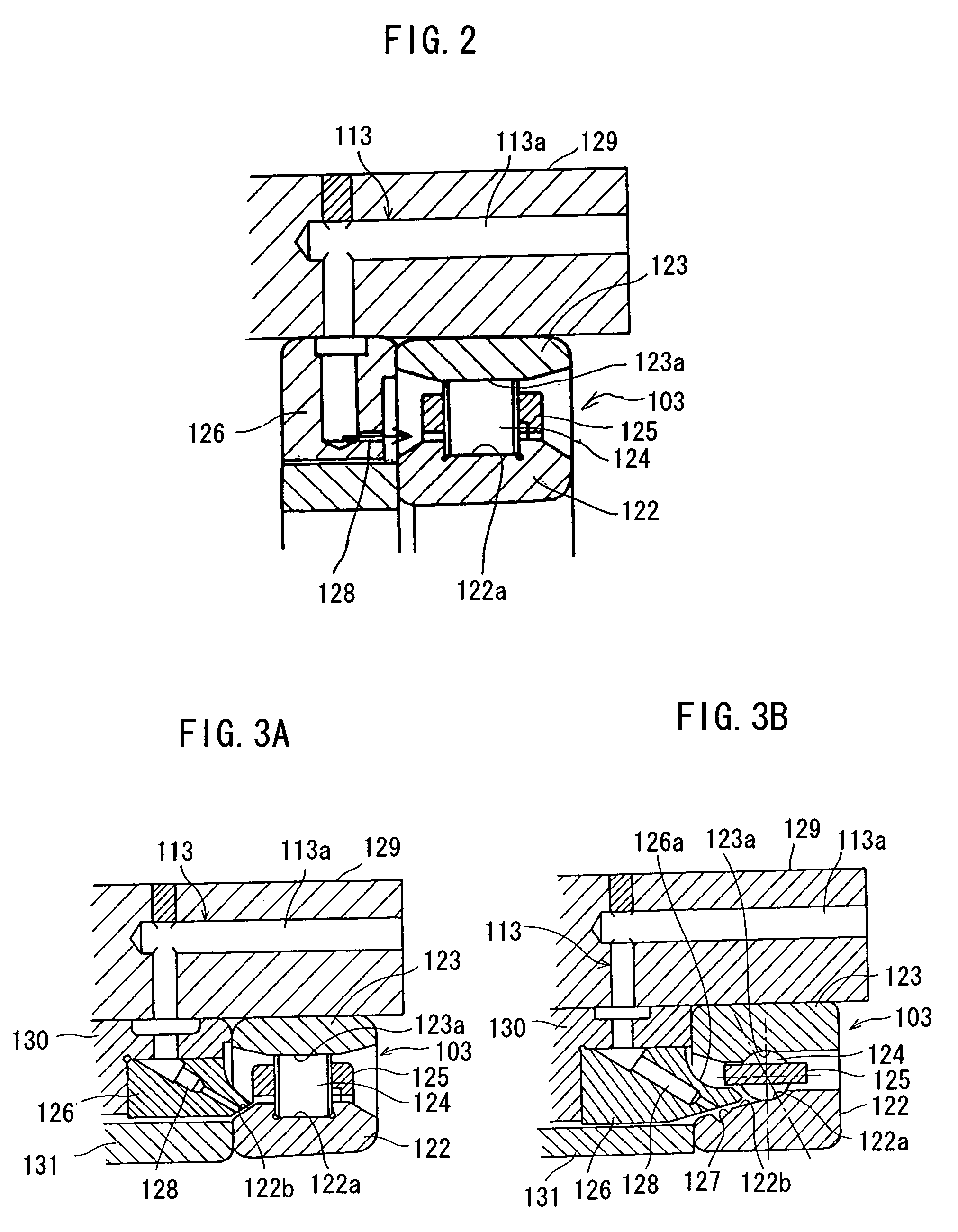
[0157]FIG. 18 illustrates an air / oil lubricating structure for the rolling bearing assembly according to a seventh preferred embodiment of the present invention. In this embodiment, the discharge passage 8 defined in the nozzle member 6A is so positioned that the air / oil mixture can be jetted into the discharge groove 7 in a direction parallel to the axial direction of the rolling bearing 1. The discharge groove 7 have side faces facing the discharge passage 8, which are formed as an inclined surface so that the air / oil mixture jetted can be guided towards the inclined surface area 2b of the inner race 2. The nozzle member 6A is fitted directly to the inner peripheral surface of the housing 9 and concurrently serves as an oute...
PUM
| Property | Measurement | Unit |
|---|---|---|
| inclination angle | aaaaa | aaaaa |
| inclination angle | aaaaa | aaaaa |
| angle of inclination | aaaaa | aaaaa |
Abstract
Description
Claims
Application Information
 - R&D
- Intellectual Property
- Life Sciences
- Materials
- Tech Scout
- Unparalleled Data Quality
- Higher Quality Content
- 60% Fewer Hallucinations
Browse by: Latest US Patents, China's latest patents, Technical Efficacy Thesaurus, Application Domain, Technology Topic, Popular Technical Reports.
© 2025 PatSnap. All rights reserved.Legal|Privacy policy|Modern Slavery Act Transparency Statement|Sitemap|About US| Contact US: help@patsnap.com


