
Tire vulcanizing device and vulcanizing method

A technology for tire vulcanization and valve control, applied in the field of tire building, can solve problems such as energy waste, low efficiency, and impact on bladder temperature stability.

Inactive Publication Date: 2021-05-14
佳美(山东)橡胶有限公司
View PDF10 Cites 0 Cited by
  • Summary
  • Abstract
  • Description
  • Claims
  • Application Information

AI Technical Summary

Problems solved by technology

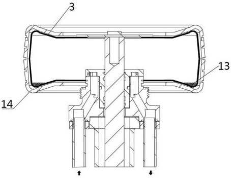
[0004] During the vulcanization process of the tire, a depression will be formed on the lower sidewall. This area is the gathering place of condensed water inside the bladder, which will cause the temperature difference between the upper and lower sides, thus affecting the consistency of vulcanization on the upper and lower sides of the tire.
The condensate discharge method is to control the timing point discharge of the intake and exhaust valves, but the efficiency of this method is too low, and it is difficult to take away all the condensate water during the vulcanization operation
And the formation, storage and evaporation process of condensed water itself is a heat exchange process, which greatly affects the temperature stability in the capsule
Moreover, it is a waste of energy to continuously fill in new superheated steam, and the utilization rate of the discharged saturated steam is very low, and it is even more harmful to the environment to discharge it into the atmosphere.
The existence of condensed water in the existing process is unavoidable and difficult to control, making it difficult to guarantee the quality of tires during the vulcanization process

Method used

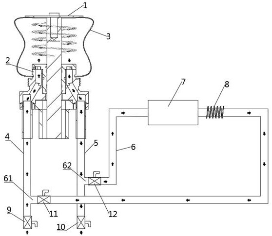
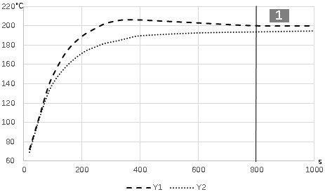

Image

  • Tire vulcanizing device and vulcanizing method
  • Tire vulcanizing device and vulcanizing method
  • Tire vulcanizing device and vulcanizing method

Examples


Embodiment Construction

[0038] In order to explain the overall concept of the present application more clearly, the following detailed description will be given by way of examples in combination with the accompanying drawings.

[0039] In the following description, many specific details are set forth in order to fully understand the application, but the application can also be implemented in other ways different from those described here, therefore, the protection scope of the application is not limited by the specific details disclosed below. EXAMPLE LIMITATIONS.

[0040] In addition, in the description of the present application, it should be understood that the terms "top", "bottom", "inner", "outer", "axial", "radial", "circumferential" and the like indicate directions or The positional relationship is based on the orientation or positional relationship shown in the drawings, which is only for the convenience of describing the application and simplifying the description, and does not indicate or ...


PUM


Abstract

The invention belongs to the technical field of tire forming, and discloses a tire vulcanizing device. The tire vulcanizing device comprises a center mechanism, a capsule, an air supply system, an exhaust system and a circulating system, the circulating system comprises a circulating pipeline, a circulating pump and high-frequency heating equipment, the circulating pipeline is provided with a first connecting end and a second connecting end, the first connecting end is in communication with an air inlet pipeline, and the second connecting end is in communication with an air outlet pipeline. Compared with the prior art, the circulating system can prevent condensed water from being formed in the capsule in the vulcanizing heating process, so that the upper and lower surfaces of the vulcanizing capsule and the upper and lower clamps are stable in temperature rise and the temperature difference is reduced, the gas temperature in the capsule is more stable, the temperature difference of contact surfaces of a tire is reduced, the fluidity difference of a rubber material is reduced, the dynamic balance uniformity is improved, and the vulcanization quality of the tire is greatly improved.

Description

technical field [0001] The application belongs to the technical field of tire building, and in particular relates to a tire vulcanization device and a vulcanization method. Background technique [0002] Tires are circular elastic rubber products assembled on vehicles or various machinery for rolling on the ground. They are usually installed on metal rims to support the body, buffer external impacts, achieve contact with the road surface and ensure the normal operation of the vehicle. . With the rapid development of the logistics industry, road transportation has also undergone changes. The state has become more and more effective in controlling overloaded and oversized vehicles, and people have higher and higher requirements for the quality of tires. [0003] As the last major process in the tire production process, the tire vulcanization process is the last step in tire quality assurance. At present, the tire vulcanization process mostly uses a combination of steam and ni...

Claims


Application Information

Patent Timeline
IPC IPC(8): B29D30/06B29C33/04B29C33/10B29C35/04B29C35/00B29L30/00
CPCB29D30/0606B29D30/0654B29D30/0662B29D2030/0617B29D2030/067B29D2030/0675B29D2030/0677
Inventor 赵瑞青许延红张玉亮
Owner 佳美(山东)橡胶有限公司
Learn More