
ZnS(Ag) scintillation detector

a scintillation detector and scintillation technology, applied in the field of scintillation detectors, can solve the problems of difficult to achieve the pulse height discrimination function of the conventional zns (ag) scintillation detector, and achieve the effect of reducing the counting of -rays and efficiently and smoothly carrying out contamination control

Inactive Publication Date: 2008-05-20
JAPAN ATOMIC ENERGY AGENCY INDEPENDANT ADMINISTRATIVE CORP
View PDF10 Cites 1 Cited by
  • Summary
  • Abstract
  • Description
  • Claims
  • Application Information

AI Technical Summary

Benefits of technology

The present invention provides a method for detecting α-rays while reducing the influence of natural radioactive nuclides and efficiently controlling contamination in nuclear facilities. This is achieved by using a ZnS (Ag) scintillation detector with a thickness that matches the energy range of α-rays from emitting nuclides to be separated. A pulse height discrimination circuit is added to the detector to identify and guide signals due to α-rays in the energy region of interest. By measuring the pulse height of signals, the detector can effectively utilize the ZnS (Ag) scintillator and reduce the influence of α-rays from progenies of radon. This results in a more accurate measurement of α-rays and improved efficiency in controlling contamination.

Problems solved by technology

The above described ZnS (Ag) scintillation detector has a problem that the counting is affected by α-rays from natural radioactive nuclides (progenies of radon) in a period that static electricity is easily generated, and in an ill-ventilated place.
However, this is difficult to be effected in the conventional ZnS (Ag) scintillation detector without the pulse height discrimination function.

Method used


Image

  • ZnS(Ag) scintillation detector
  • ZnS(Ag) scintillation detector
  • ZnS(Ag) scintillation detector

Examples


example

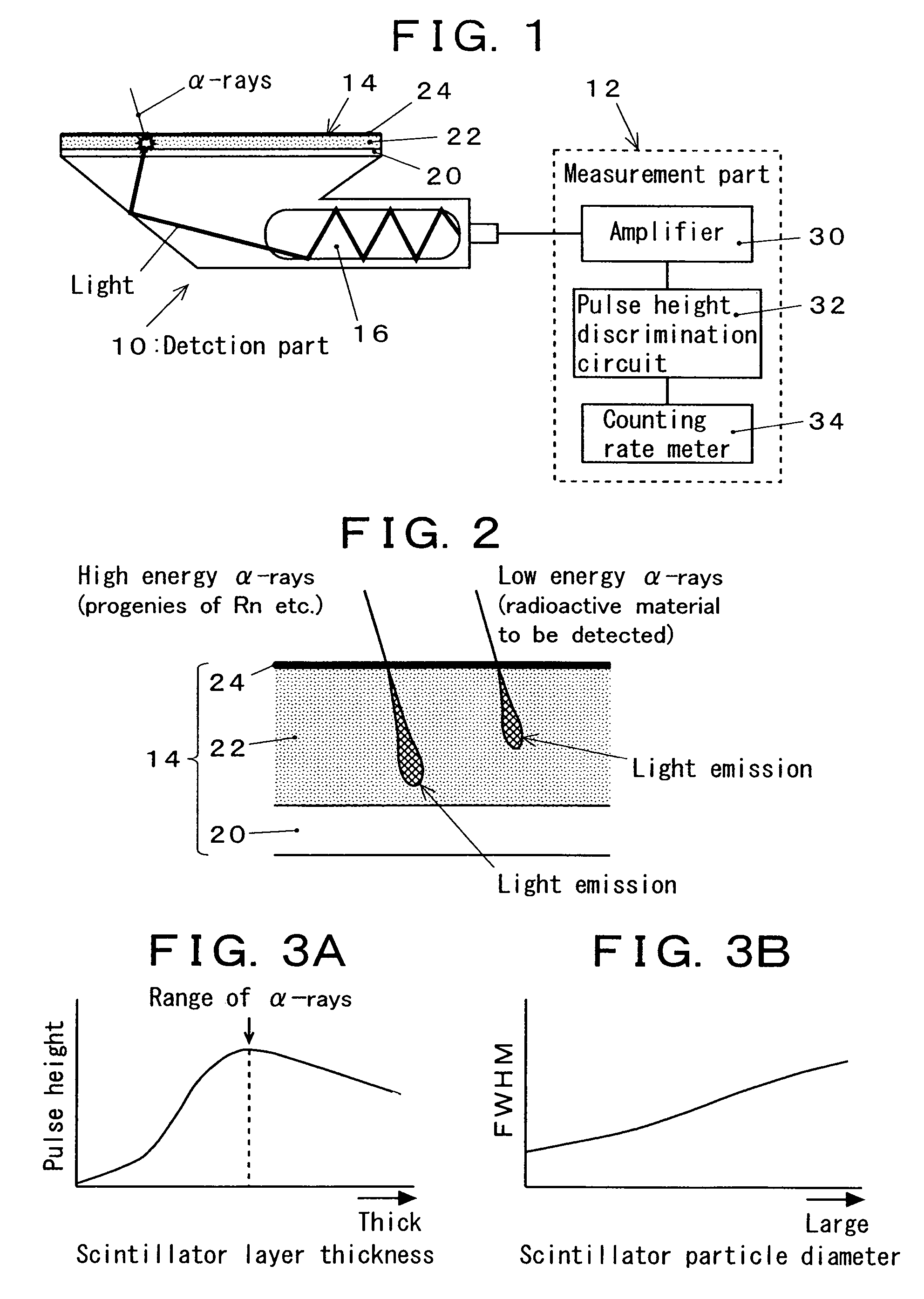
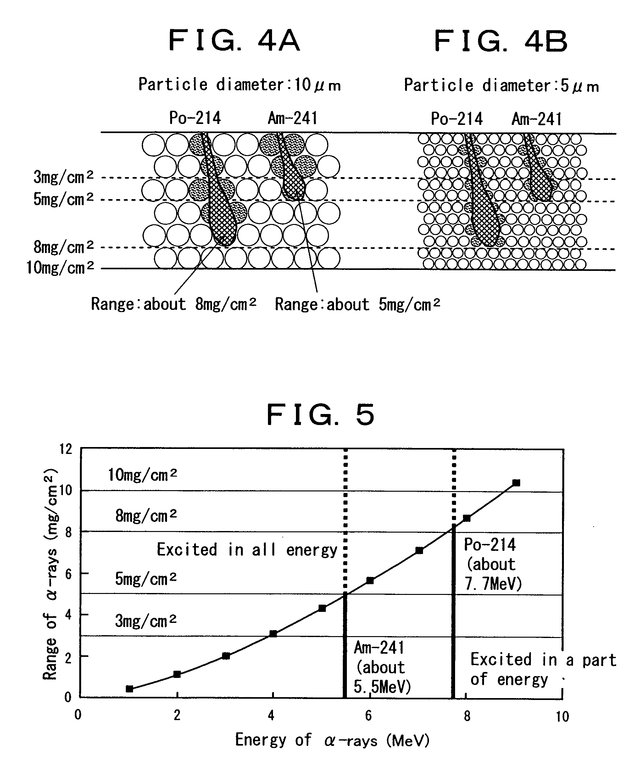
[0022]FIGS. 4A and 4B schematically show a relationship between the scintillator layer thickness, the particle diameter of scintillator, and the quantity of emitted light. FIG. 4A shows the case where the particle diameter of scintillator is large (for example 10 μm), and FIG. 4B shows the case where the particle diameter of scintillator is small (for example 5 μm). Here, the α-ray emitting nuclide to be separated is Po-214. The energy of α-rays of Am-241 (the radioactive material to be detected) is about 5.5 MeV (range: about 5 mg / cm2), and the energy of α-rays of Po-214 (progeny of radon) is about 7.7 MeV (range: about 8 mg / cm2). In FIGS. 4A and 4B, the particles denoted by dots represent the ZnS (Ag) scintillators which are excited by the incidence of α-rays and emit light. As can be seen from FIGS. 4A and 4B, in the case of the scintillator layer with a thickness of 5 mg / cm2 or less, the number of scintillators which are made to emit light by α-rays of Am-241 is not significantl...


PUM


Abstract

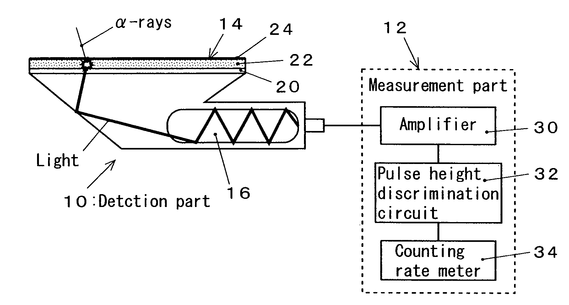
A ZnS (Ag) scintillation detector comprises a ZnS (Ag) scintillators layer 22 which is excited by incident α-rays and emits a scintillator light, a photomultiplier tube 16 which converts the scintillator light into an electric pulse signal, and a counting rate meter 34 which counts the obtained pulse signal. The scintillator layer has a thickness which is not less than a range of α-rays from α-ray emitting nuclides (natural radioactive nuclides) to be separated, which enables energy absorption of α-rays from the α-ray emitting nuclides to be separated to entirely occur in the scintillator layer, and which enables light shielding of the scintillator light generated in the scintillator layer by the scintillator layer itself to be neglected. A pulse height discrimination circuit 32 is further provided in a preceding stage of the counting rate meter. Thereby, the effect of the natural radioactive nuclides can be reduced and the contamination control can be efficiently and smoothly performed.

Description

FIELD OF THE INVENTION[0001]The present invention relates to a scintillation detector in which a ZnS (Ag) scintillator is used so as to make it possible to perform energy discrimination of α-rays. The ZnS (Ag) scintillation detector is capable of reducing the effect of natural radioactive nuclides on measurement, and hence, is useful as an α-ray survey meter used for the contamination control, for example, in the inside of nuclear facilities.BACKGROUND OF THE INVENTION[0002]The ZnS (Ag) scintillation detector is relatively durable and inexpensive, and hence, is most extensively used for the radiation control of α-rays in nuclear facilities and the like. The ZnS (Ag) scintillator is a crystal (powder) with a trace of Ag as an activator added to ZnS, and emits scintillator light when excited by α-rays (see, for example, “Nuclear Energy Handbook (new edition)”, 3.4 Measurement of Radioactive Rays, p. 73 to 78, published on Mar. 30, 1989, by Ohm-sha). The conventional detector measures ...

Claims


Application Information

Patent Timeline
Patent Type & Authority Patents(United States)
IPC IPC(8): G01T1/20G01T1/208
CPCG01T1/20
Inventor HASEGAWA, ICHIROIZAKI, KENJIKOBAYASHI, HIROHIDEINO, KAZUOKANAZAWA, NOBUYUKI
Owner JAPAN ATOMIC ENERGY AGENCY INDEPENDANT ADMINISTRATIVE CORP
Learn More