Optical module and method for manufacturing the same

a technology of optical modules and manufacturing methods, applied in the field of optical modules, can solve the problems of poor coupling efficiency, large positional deviation, and small correction, and achieve the effects of improving coupling efficiency, high positional precision, and high precision

Inactive Publication Date: 2008-05-20
ROHM CO LTD
View PDF15 Cites 18 Cited by
  • Summary
  • Abstract
  • Description
  • Claims
  • Application Information

AI Technical Summary

Benefits of technology

[0020]Moreover, by repeating the above-mentioned steps (d) to (e) may be further at least once, even in the case of differences existing in heat application history, the correcting processes of two or three times make it possible to carry out a complete positioning operation. So that it may be possible to provide high positional precision with an improved coupling efficiency.
[0021]Furthermore, between the above-mentioned steps (b) and (c), a step in which the optical transmission member is shifted by using the driving mechanism based on an amount that is preliminarily predicted as an amount of deviation in the Y direction caused by the securing process of the optical transmission member may be carried out, with the above-mentioned steps (d) to (e) being omitted. Thereby, it becomes possible to carry out assembling processes with high precision without the necessity of carrying out any correcting process.
[0022]That is, as described above, although a fine deviation occurs due to heat applied thereto upon securing the optical transmission member, the deviation is virtually the same upon application of the same heat. Therefore, in the case of mass production, the amount of deviation can be predicted to a certain extent. So that, by preliminarily obtaining the predicted amount, the optical transmission member is preliminarily shifted from the optimal position based on the corresponding amount of deviation prior to the securing process with the soldering material, and then fixedly secured thereto. Thus, it is possible to carry out positioning processes with high precision without conducting any correcting process after the securing process, and consequently to improve the coupling efficiency.
[0023]Here, the above-mentioned steps may be carried out outside a box member, and after the optical transmission member has been fixedly secured

Problems solved by technology

However, in the case when, after the positioning process using these methods, an optical transmission member such as an optical fiber is secured, a positional deviation actually occurs during the securing process.
However, for example, in the case of the securing process through welding by a YAG laser, there occurs a great positional deviation during the securing process, and little correction is made.
Additionally, since the correction of the amount of deviation cannot be carried out quantitatively, the amount of deviation after the securing process reaches approximately 0.7 μm in average, as shown in FIG. 11C, resulting in a serious reduction in the yield.
Moreover, since the correction process is carried out by preparing an increased number of welding points and by pulling toward the points, the number of corrections is limited to several times.
In contrast, in the case when the securing process is carri

Method used


Image

  • Optical module and method for manufacturing the same
  • Optical module and method for manufacturing the same
  • Optical module and method for manufacturing the same

Examples


Embodiment Construction

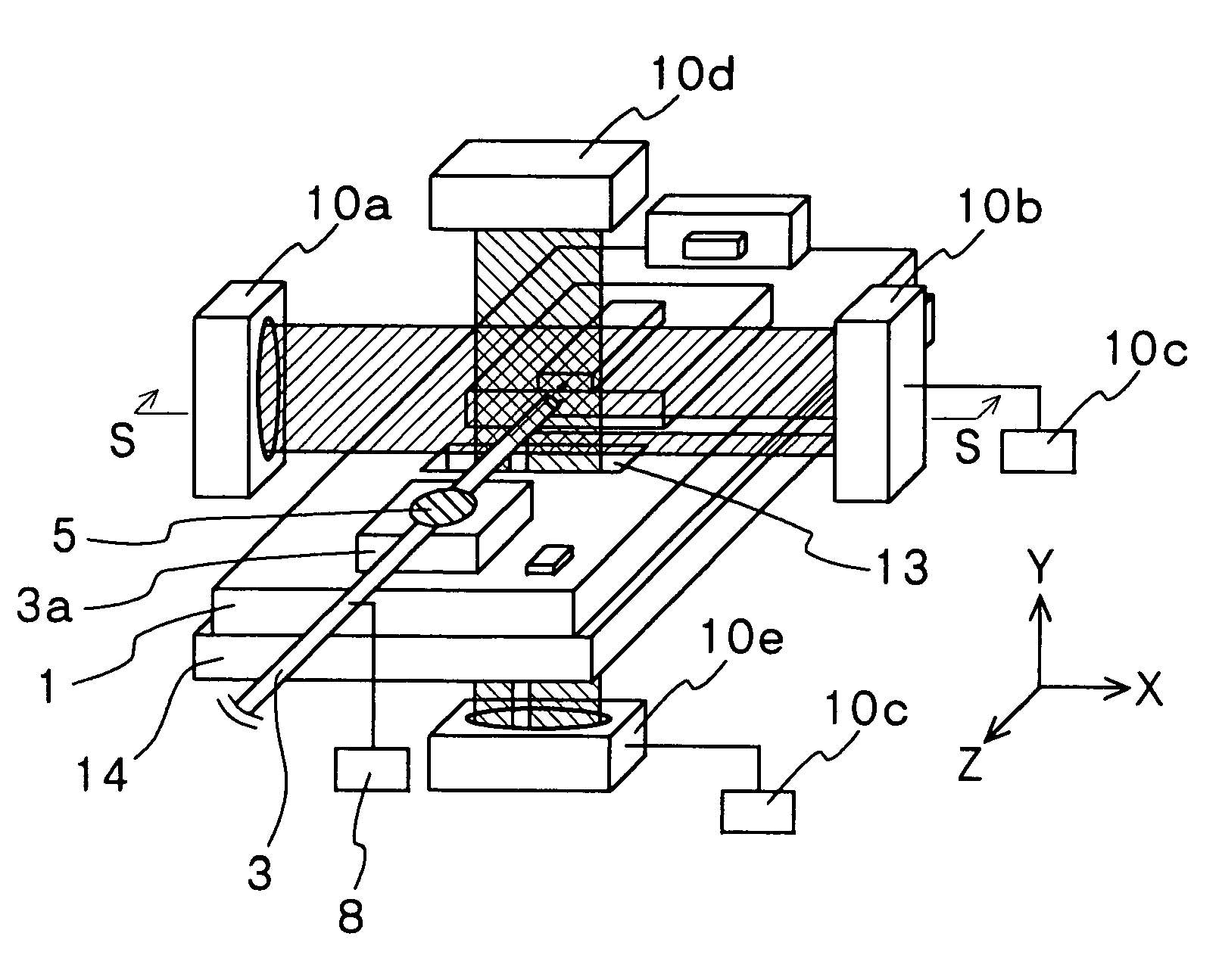
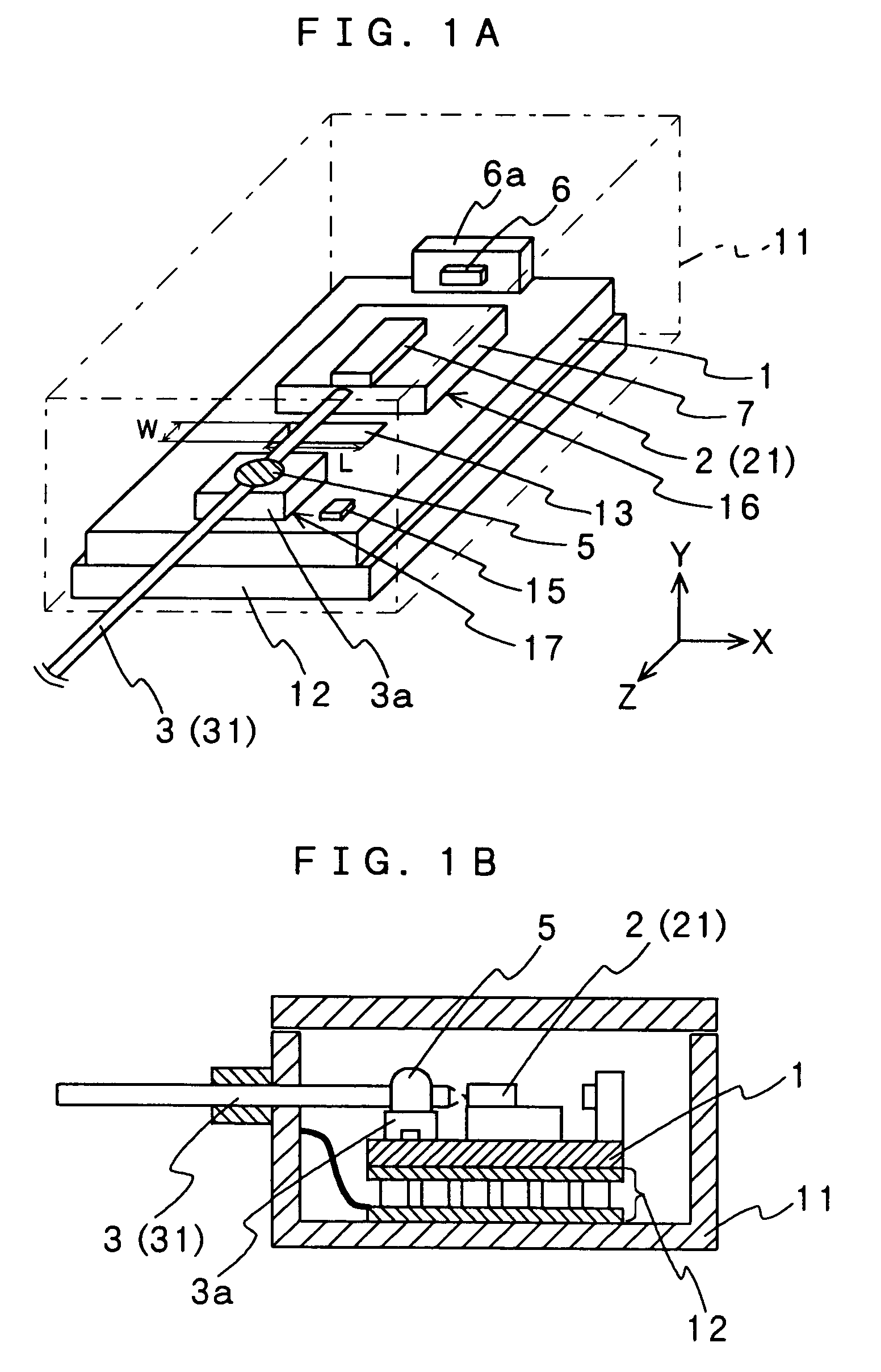
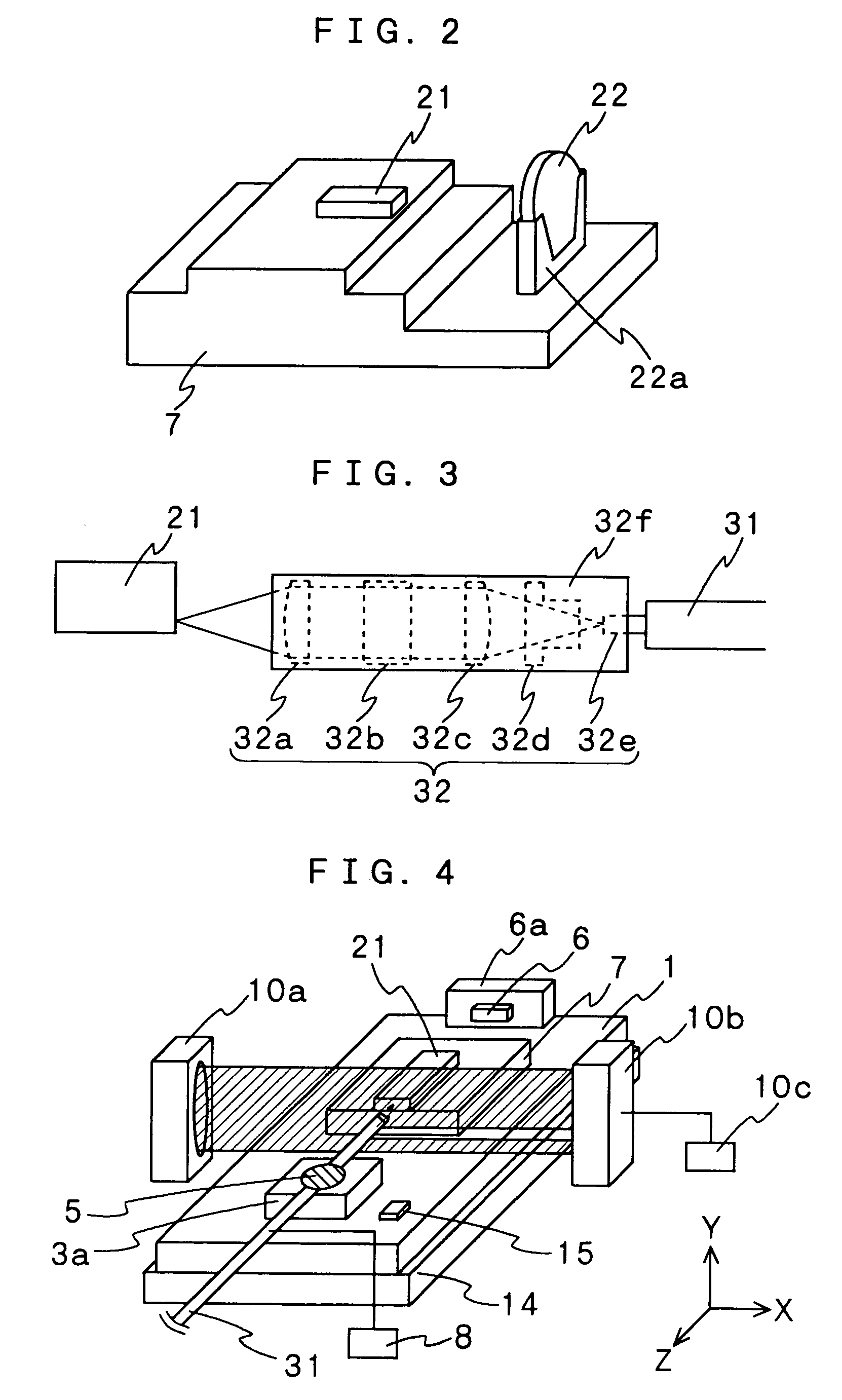
[0037]Referring to FIGS. 1A and 1B, the following description will discuss an optical module in accordance with the present invention. FIGS. 1A and 1B show one embodiment of an optical module in accordance with the present invention, and are a perspective view that explains an optical module for use in an exciting light source used for an EDFA or the like, from which a box member has been removed, and a cross-sectional view that shows the entire structure thereof. An optical module in accordance with the present invention has following arrangement.

[0038]In which an optical element 2 (a semiconductor laser chip 21 in an example shown in FIG. 1) is fixedly secured to a substrate 1, and an optical transmission member 3 (an optical fiber 31 in the example shown in FIG. 1), which is coupled to the optical element 2, is fixedly secured to the substrate 1. Further, this assembled member is secured to the inside of a box member 11 made of trademark Kovar, Cu—W, or the like through a Peltier...


PUM


Abstract

An optical element and an optical transmission member are fixedly secured onto a substrate so as to be coupled to each other. In this substrate, a through hole is formed between an optical element secured portion and an optical transmission member secured portion. In an attempt to assemble these optical transmission member and optical element so as to make the coupling at an optimal position, first, the position of the optical transmission member is adjusted to an optimal position, and after measuring the position by a laser micrometer, the optical transmission member is fixedly secured thereto by using a soldering material. Thus, measurements are again carried out by the laser micrometer to detect an amount of deviation from the measured value before the securing process, and the secured portion is again fused so that the optical transmission member is shifted based on the amount of deviation, and again fixedly secured thereon.

Description

FIELD OF THE INVENTION[0001]The present invention relates to an optical module in which an optical element and an optical transmission member are assembled and a manufacturing method thereof. More specifically, the present invention relates to an optical module in which the optical element and the optical transmission member are aligned in an appropriate positional relationship with high precision to provide high reliability and high yield, and a manufacturing method thereof.BACKGROUND OF THE INVENTION[0002]With respect to an EDFA (Erbium-Doped Fiber Amplifier) or the like which is used for, for example, a relay point in a main-line transmission path, and amplifies a signal, an optical module having a semiconductor laser and an optical fiber assembled therein is used as an exciting light source. The optical module of this type has a structure shown in FIG. 11A. In other words, a substrate 1 is placed on a Peltier element 12 in a box member 11, and a semiconductor laser chip 21 is fi...

Claims


Application Information

Patent Timeline
IPC IPC(8): G02B6/30G02B6/42
CPCG02B6/4238G02B6/4239
Inventor NAWAE, SHUICHIICHIHARA, JUN
Owner ROHM CO LTD
Why Eureka
Try Eureka