Waveguide structure and method of manufacturing the same

a manufacturing method and waveguide technology, applied in the direction of optical waveguide light guides, instruments, nanotechnology, etc., can solve the problems of large bending loss, weak coupling effect of light to the core by the difference in refractive index, and restriction on the bending size of the waveguide, so as to improve coupling with optical fiber, the effect of small propagation loss and small radius of curvatur

Active Publication Date: 2008-05-20
NEC CORP
View PDF23 Cites 8 Cited by
  • Summary
  • Abstract
  • Description
  • Claims
  • Application Information

AI Technical Summary

Benefits of technology

[0013]It is therefore an object of the present invention to provide a waveguide structure and a manufacturing method of the same, wherein the weaknesses of the above-mentioned conventional waveguide structures are removed, the radius of curvature can be lessened to less than or equal to 10 μm, the propagation loss is small, and it is possible to have better coupling with optical fiber.
[0016]It is a further object of the invention to provide a coupled waveguide where a complete coupling length is short (several dozen μm) so as to shorten the length of a device using this significantly. Furthermore, it is yet another object of the invention to provide a waveguide structure capable of realizing a distributed reflector (Bragg reflection) mechanism without a need for a special process.

Problems solved by technology

Therefore, the confinement effect of light to the core by the difference in refractive index is weak, and a large bending loss occurs when the waveguide is tried to be bent at a radius of curvature of about less than or equal to 1 mm.
Accordingly, when used in an optical integrated circuit, there is a restriction on the bending size of the waveguide and there was the problem that the optical circuit could not be made very small.
However, the cross-sectional area of the core is small at 0.2 μm×0.5 μm, and it was difficult to effectively insert light from the outside.
Also, because fundamentally the structure of the cross section differs horizontally and vertically, in Si-wire waveguides, there is polarization dependence, and it was not possible to insert and use partway through a waveguide not having polarized wave dependence, such as optical fiber.

Method used


Image

  • Waveguide structure and method of manufacturing the same
  • Waveguide structure and method of manufacturing the same
  • Waveguide structure and method of manufacturing the same

Examples


Embodiment Construction

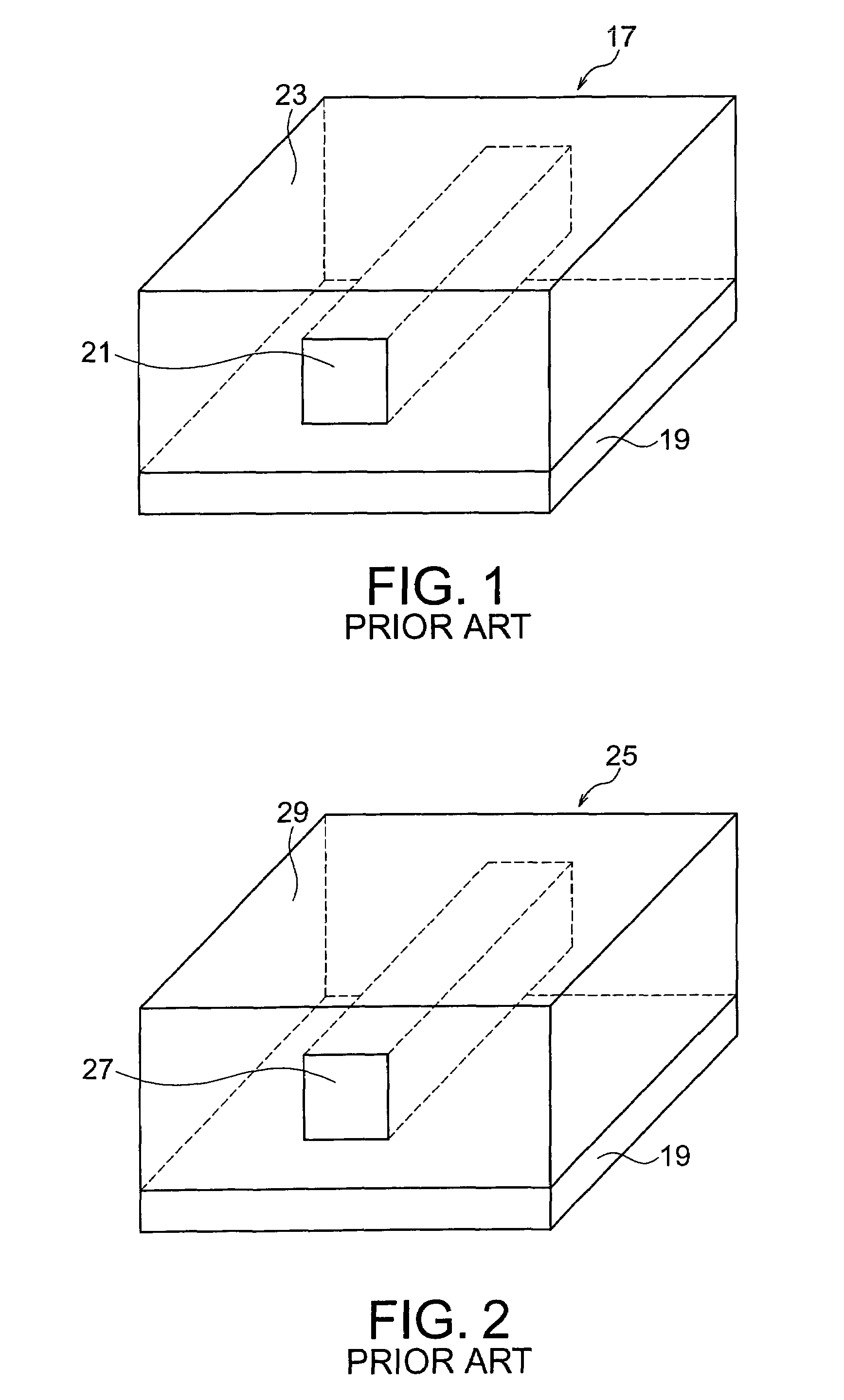
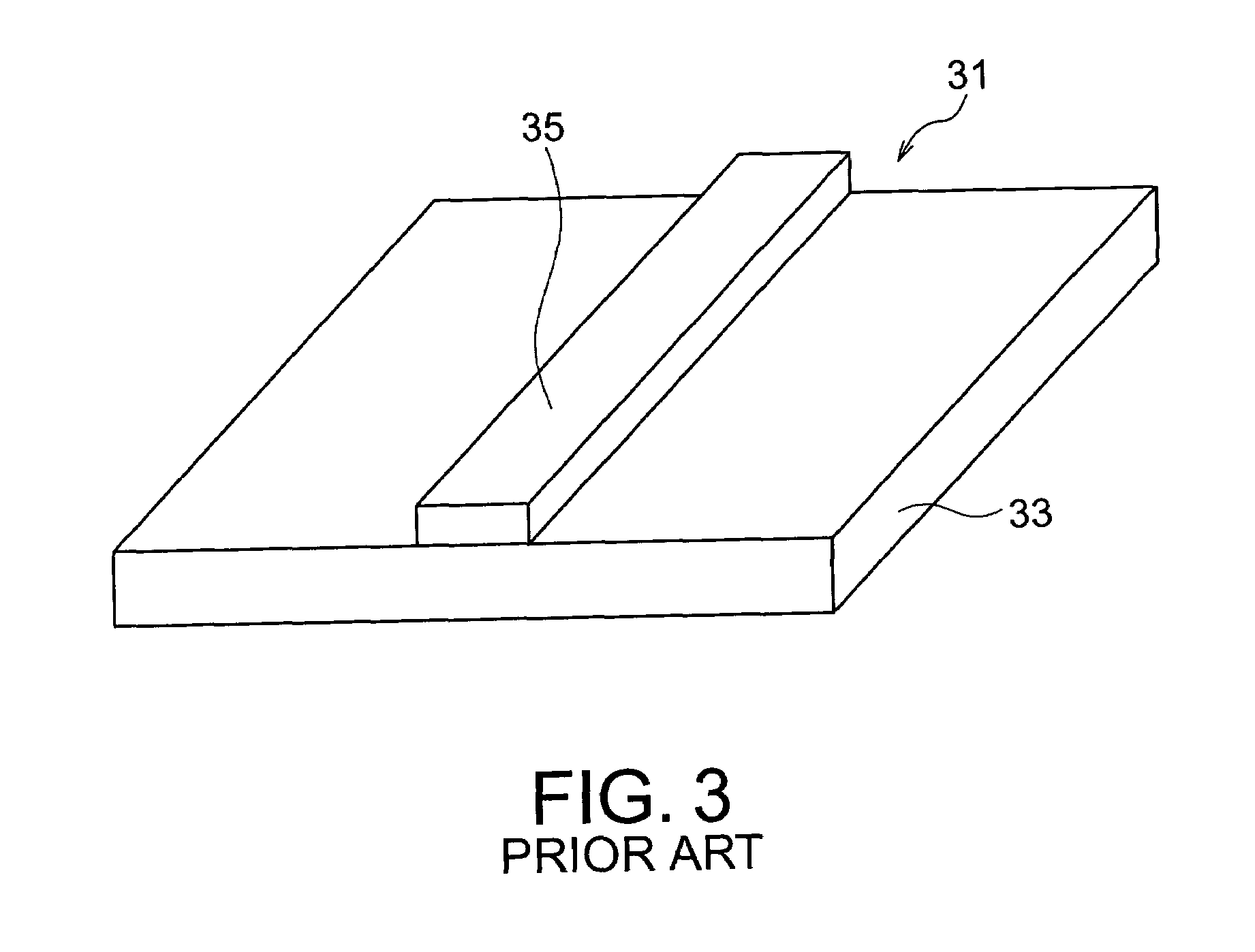
[0039]For a better understanding of the present invention, waveguides according to the related art will be explained using FIGS. 1 to 3 before explaining the embodiments of the present invention.

[0040]With reference to FIG. 1, a silica-based waveguide 17 of (i) has a core 21 and a cladding layer 23 made of silica glass (SiO2) formed on a substrate 19. By doping the core 21 with Ge or the like, a difference is made in refractive index between the core 21 and the cladding layer 23 of about 2 to 5% in order to guide light. It is widely used for a planer lightwave circuit (PLC). An AWG, which is used widely for communications, is achieved using this technique.

[0041]With reference to FIG. 2, a polymer-based waveguide 25 in (ii) has a core 27 and a cladding layer 29, both made of a polymer material such as PMMA or polyimide: a minute difference is made in refractive index between the material forming the core 27 and the material forming the cladding layer 29 in order to guide light.

[0042]...


PUM

PropertyMeasurementUnit
refractive indexaaaaaaaaaa
coupling lengthaaaaaaaaaa

Abstract

A waveguide structure having a cross-sectional structure wherein Si is in the center and it is surrounded by a peripheral material, which is either SiO2 or a polymer material. The above-mentioned peripheral material functions as a cladding.

Description

BACKGROUND OF THE INVENTION [0001](1) Field of the Invention[0002]The present invention relates to a new structure and manufacturing method of a waveguide, and more particularly, to a structure and manufacturing method of a waveguide that can be used for an optical integrated circuit.[0003](2) Description of the Related Art[0004]Conventionally, waveguide structures used for optical integrated circuits include, (i) silica-based waveguides, as shown in Japanese Laid-Open Patent Publication (JP-A) No. 2002-14242A and Japanese Laid-Open Patent Publication (JP-A) No. 2001-133648A (hereinafter referred to respectively as Reference 1 and Reference 2), (ii) polymer-based waveguides, as shown in Japanese Laid-Open Patent Publication (JP-A) No. H10-3013A (hereinafter referred to as Reference 3), and (iii) Si-wire waveguides, as shown in Japanese Laid-Open Patent Publication (JP-A No. 2002-323633 (hereinafter referred to as Reference 4).[0005]The above-mentioned (i) silica-based waveguides eac...

Claims


Application Information

Patent Timeline
Patent Type & Authority Patents(United States)
IPC IPC(8): G02B6/10G02B6/12G02B6/122G02B6/13
CPCB82Y20/00G02B6/1221G02B6/1223G02B2006/121
Inventor YAMADA, HIROHITO
Owner NEC CORP
Why Eureka
Try Eureka