[0003]This invention relates to the field of plumbing traps and strainers, specifically to a plumbing
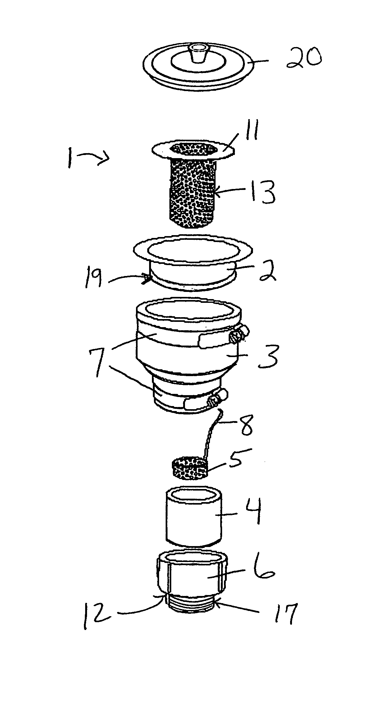
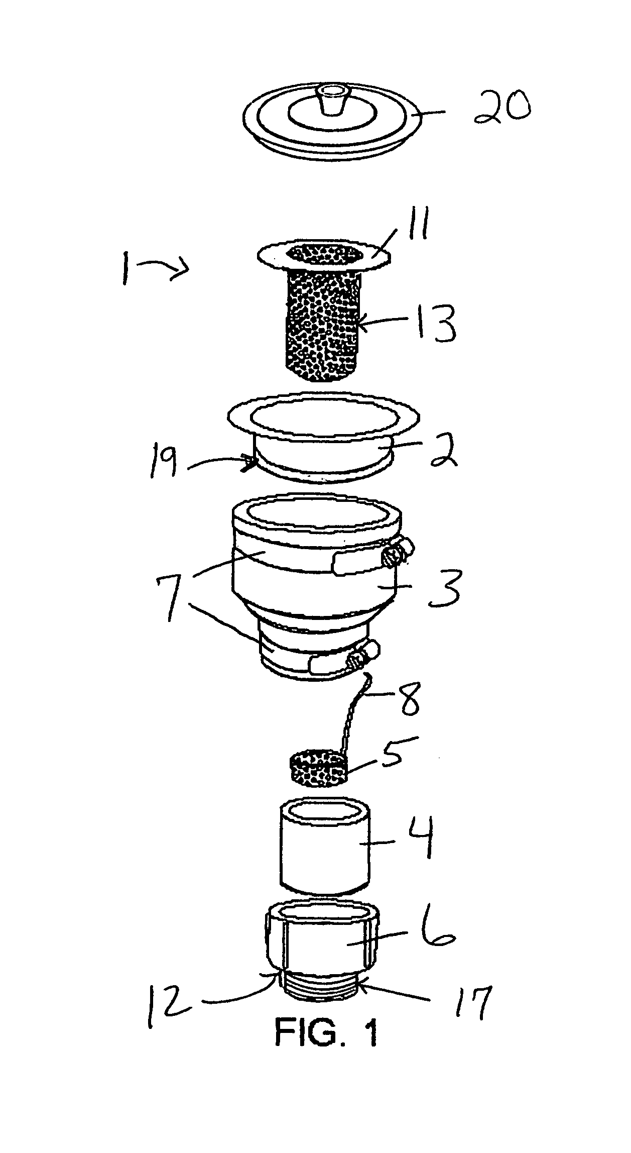
assembly that is used under a plumbing fixture (sink, tub, etc.) to prevent drain blocking clogs. It has two strainers and structure for supporting them in desired positions of use between the plumbing fixture and the drain piping below it, with one strainer located above the other. The first strainer has a larger debris-catching volume than the second strainer and is in a superior position to the second strainer. Both have openings on their side and bottom surfaces configured to catch all debris, including hair and
food particles, as well as dimensioned to allow oils and
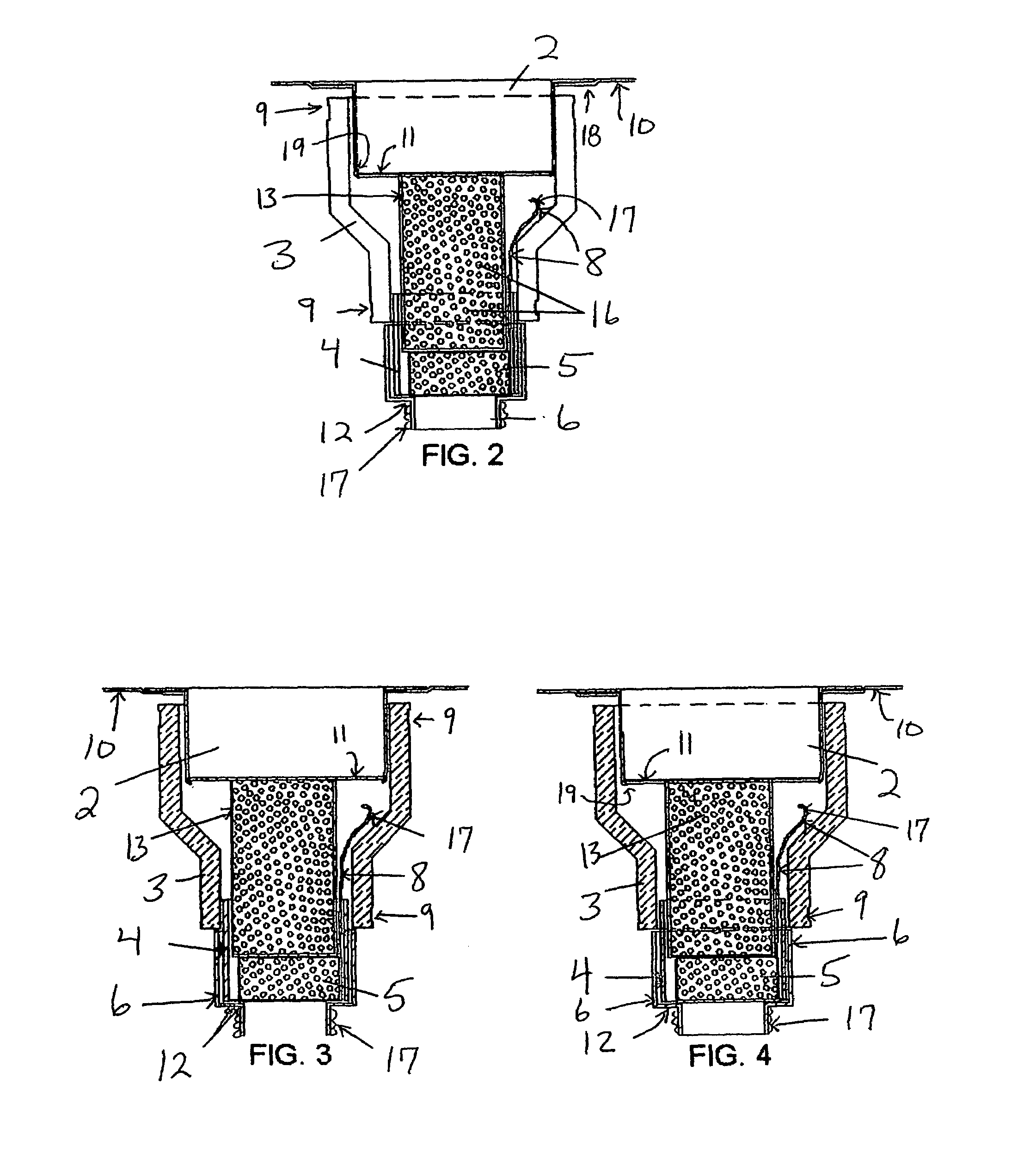
grease to be rinsed substantially from the collected debris. When the first strainer becomes filled with debris and / or wastewater flow through it begins to slow, it is lifted upwardly through the drain opening in the associated plumbing fixture and cleaned by emptying its contents into a dry waste receptacle. While the first strainer is removed from its preferred position of use, the second strainer is typically left in place to catch all debris in any standing water or other waste fluid passing through the plumbing fixture's drain opening. Should the openings in the first strainer become sufficiently blocked with debris to cause standing water in the associated plumbing fixture, the first strainer can be drawn upwardly through the standing water, with the second strainer functioning in a back-up role to catch any debris in the standing waste fluid as it enters into the plumbing fixture's drain opening and before it passes into a connected trap or drain piping, thus avoiding the risk of such debris building up sufficiently in the trap or drain piping to produce a fluid-blocking clog in a position that would be
time consuming and / or costly to unblock. An important
advantage of the present invention
system is that both strainers are inserted and removed through the
discharge opening of an associated plumbing fixture from a location above it. Thus, the person using a plumbing fixture having a connected present invention assembly does not have to bend over or drop to the knees to remove collected debris from either strainer. The first strainer can be easily removed via finger engagement with a protruding stub built into its interior surface near to its open top end. The second strainer has an elongated
handle that permits easy withdrawal of the entire second strainer after the first strainer has been removed. Also, the
handle of the second strainer is sufficiently short and has a bent configuration that allows it to clear the primary strainer above it so that when the second strainer is in its preferred position of use, it does not unseat the first strainer from its preferred positioning, whereby optimal debris catching is achieved.
[0005]Debris traps for wastewater entering drain piping from a plumbing fixture are necessary to prevent the formation of fluid-blocking clogs that cause slow evacuation of wastewater from the plumbing fixture and / or wastewater accumulation in the plumbing fixture. P-traps or S-traps are typically placed under the fixture from which the wastewater is drained and clean out procedures are accomplished only from under the fixture, a
disadvantage for those with
arthritis, knee or hip injury, and advanced age. Also, special tools are usually needed to remove a P-trap or S-trap for cleaning, and strength may be required to accomplish the task, again a disadvantage for the infirm, injured, and elderly. Another prior art means of catching wastewater debris are strainers sitting in the uppermost portion of the drain piping connected to a plumbing fixture, such as the common kitchen sink strainer basket. However, many of them are shallow and not effective in high-volume wastewater applications, and / or do not have a filtering configuration that is effective in
trapping hair and debris. Further, there is the issue of standing water, wherein once a strainer basket is removed, any standing water or other waste fluid in a plumbing fixture, along with associated debris, immediately moves through the plumbing fixture's drain opening and enters the drain piping below, where it poses a risk for creating a drain blocking clog in a position that would be difficult or expensive to remove.
[0007]The primary object of this invention is to provide a plumbing assembly with two strainers that are stacked vertically for efficient
trapping of
food particles, hair, and
solid debris from waste fluid, and wherein
insertion and removal of the strainers from the
discharge opening in a plumbing fixture is from a location above it. It is also an object of this invention to provide a plumbing assembly wherein the lower strainer is configured and dimensioned to avoid interfering with proper seating of the upper strainer in its desired position of use. Another object of this invention is to provide a plumbing assembly with strainers that can be rapidly set into their desired positions of use, and rapidly removed for cleaning without the use of tools. It is a further object of this invention to provide a plumbing assembly that is lightweight, durably constructed, and made from
corrosion-resistant components. It is also an object of this invention to provide a plumbing assembly with support structure for the strainers that is made from commonly available components for lower manufacturing cost. It is a further object of this invention to provide a plumbing assembly with support structure that can be easily assembled during installation.
[0009]The description herein provides preferred embodiments of the present invention but should not be construed as limiting its scope. For example, variations in the width dimension of the compression strap used to secure the upper end of the
reducer coupling to the bottom of a sink
flange that is otherwise typically used as a part for mounting a food disposal unit, the width dimension of the compression strap used to secure the lower end of the
reducer coupling to the short adaptor, the length of the handle as long as it clears the primary strainer and does not unseat it, the number of holes in each strainer, the width dimension of the handle as long as it offers sufficient strength for lifting the strainer body filled with waste fluid debris without bending or otherwise deforming and is not so bulky as to add unwanted weight, and the wall thickness of each strainer as long as they are sufficiently strong and sturdy without unnecessary material waste, other than those shown and described herein, may be incorporated into the present invention. Thus the scope of the present invention should be determined by the appended claims and their legal equivalents, rather than being limited to the examples given.

