Evaporation control for a fluid supply

a technology of fluid supply and evaporation control, which is applied in the field of clinical chemistry, can solve the problems of increasing the cost per test, increasing the overall cost and complexity of the analyzer, and affecting the accuracy of the results, so as to minimize the exposed wet surface area, minimize the cost and complexity, and maximize the path length

Inactive Publication Date: 2008-05-27
ORTHO-CLINICAL DIAGNOSTICS
View PDF13 Cites 6 Cited by
  • Summary
  • Abstract
  • Description
  • Claims
  • Application Information

AI Technical Summary

Benefits of technology

[0016]An advantage of the present invention, using an evaporation straw or similar evaporation control means, is substantially lower cost and complexity to a clinical analyzer design, while permitting large diameter supply bottles to be utilized without capping of same for each use. In addition, a fluid supply having evaporation control features in accordance with the present invention is in fact superior than most known bottle designs having pierceable caps.
[0017]Employing t

Problems solved by technology

Clinical chemistry analyzers, such as those manufactured by Abbott Laboratories and the Johnson and Johnson Company, among others, having reagent supplies on board for use in preparing wet immunoassays are sensitive to the effect of reagent evaporation, thereby causing prediction shifts with storage time.
This method of control requires a large reagent storage area within the analyzer and increases the cost per test as more fluid is used in each test.
This mechanism and its associated control adds significantly to the overall cost and complexity of the analyze

Method used


Image

  • Evaporation control for a fluid supply
  • Evaporation control for a fluid supply
  • Evaporation control for a fluid supply

Examples


example a

Comparison of Evaporation Effects Based on Differing Straw Lengths and Prior Known Evaporation Controls

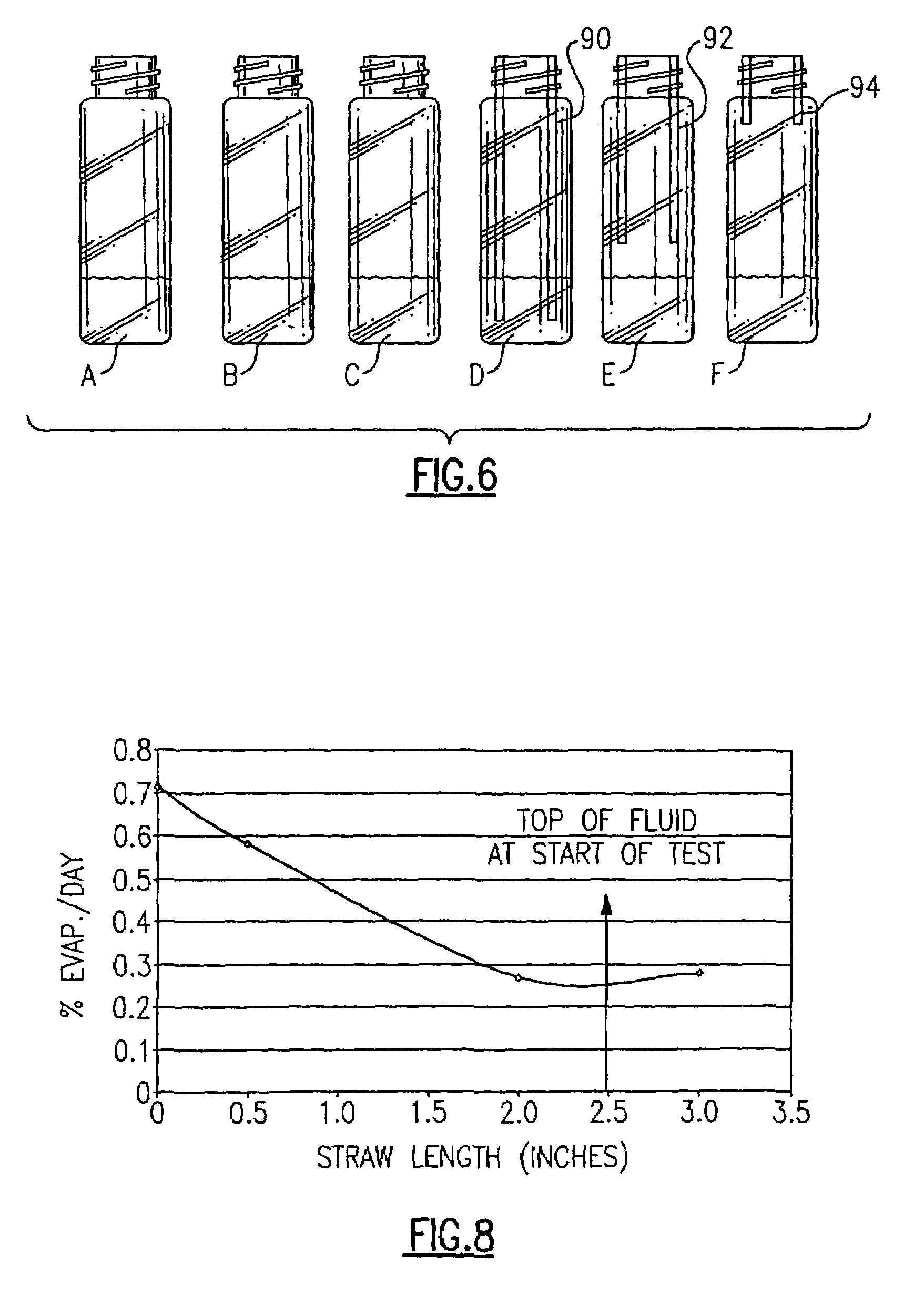
[0043]As a prologue to the fluid supply illustrated in FIGS. 1-5, and to further point out the inventive concepts achieved by the evaporation control member, a first plurality of different 20 mL bottles, see FIG. 6, were each filled, according to this example, with 4 mL each of a solution of 0.004% Magenta dye in water. This solution produces a measurable absorbance of roughly 2 AU at a wavelength of 540 nanometers. By tracking changes in the absorbance of the solution over time using a spectrophotometer or similar apparatus, changes in the absorbance of the solution and effectively, evaporation rates can be extrapolated which provides a basis for tangible comparison.

[0044]In this example, six (6) bottle designs were tested and compared. These bottles are shown in FIG. 6 and included the following: a standard open bottle, herein designated A, a bottle having a plastic pierceable ca...

example b

Comparison of Wetted Surface Area and Diffusion Length on Evaporation

[0053]As a further example, 4 mL of sample fluid was placed into another plurality of bottles as shown in FIG. 9. The sample fluid for purposes of this example was an identical solution, as defined in Example A, of 0.004% Magenta dye in water. For purposes of this example, different bottle-types, each having open ends, but different geometries, were compared. The first bottle, herein designated as G, is similar to the bottle A from the preceding example. This bottle is an open top bottle having a height of 85 mm, an inside diameter of 19.5 mm and a top neck portion. The second bottle, herein designated H, has an inside diameter of 19.5 mm, but the total height of the bottle is only approximately 45 mm. The third and fourth bottles, herein designated I and J, respectively, were 85 mm in height but had a reduced (9.8 mm) inside diameter. Bottle J was further distinguished in that only 2 mL of fluid were used in order...


PUM


Abstract

Evaporation control for a fluid supply, such as used in a clinical analyzer, can be provided by utilizing a straw-like insert which is disposed into a fluid-containing bottle. The straw provides an increased diffusion length or “stagnant” zone. The bottle can also be configured to effectively reduce evaporation in a similar manner by providing a narrowed diameter prior to the fluid retaining portion of the bottle and by increasing the distance between the top of the bottle and the top of the fluid surface.

Description

[0001]This application claims priority, under 35 U.S.C.§119(e), of U.S. Provisional Application Ser No. 60 / 369,220, filed Apr. 1, 2002, entitled: “Evaporator Control For A Fluid Supply”.FIELD OF THE INVENTION[0002]This invention relates generally to the field of clinical chemistry, and more particularly to a fluid supply for a clinical analyzer or similar apparatus having improved features for controlling evaporation.BACKGROUND OF THE INVENTION[0003]Clinical chemistry analyzers, such as those manufactured by Abbott Laboratories and the Johnson and Johnson Company, among others, having reagent supplies on board for use in preparing wet immunoassays are sensitive to the effect of reagent evaporation, thereby causing prediction shifts with storage time. The change in the concentration of reagents that occurs with evaporation causes the reaction concentrations in a reaction vessel, such as a cuvette, to change, thereby causing the prediction shifts. Assay systems with a large reagent co...

Claims


Application Information

Patent Timeline
IPC IPC(8): B01L3/02B01L3/08G01N35/00
CPCB01L3/08B01L2200/026Y10T436/2575B01L2200/16G01N2035/00287B01L2200/142
Inventor ARTER, THOMASSCHWALLIE, SCOTTHASSETT, JAMESLOVE, JAMESSHAW, JAMES D.MORAN, JR., DONALD J.WITKOWSKI, ROBERT T.MCFEATERS, MALINDA L.
Owner ORTHO-CLINICAL DIAGNOSTICS
Why Eureka
Try Eureka