Compact dedusting apparatus

a dedusting apparatus and compact technology, applied in the field of compact dedusting apparatus, can solve the problems of affecting the flow of materials, etc., and achieve the effect of improving the air flow characteristics

Active Publication Date: 2008-06-03
PELLETRON CORP
View PDF11 Cites 68 Cited by
  • Summary
  • Abstract
  • Description
  • Claims
  • Application Information

AI Technical Summary

Benefits of technology

[0011]It is an object of the invention to overcome the disadvantages of the prior art by providing a compact dedusting apparatus that has improved air flow characteristics for the inlet of clean air into the housing and the discharge of dirty air from the housing.
[0012]It is another object of this invention to provide an effective compact dedusting apparatus that can thoroughly clean a flow of particulate material of dust particles and other contaminants immediately prior to the particulate material being used.
[0013]It is still another object of this invention to provide an enhanced wash deck configuration to increase the capacity of a compact dedusting apparatus.

Problems solved by technology

As these materials move through the pipes, considerable friction is generated not only among the particles themselves, but also between the tube walls and the particles in the stream.
In turn, this friction results in the development of particle dust, broken particles, fluff, streamers (ribbon-like elements that can “grow” into quite long and tangled), glass fibers in glass filled products, that can impede the flow of materials or even totally block the flow.
Using plastics as an example, such foreign material could have a detrimental effect on the finished product.
Specifically, foreign material different in composition from the primary material, such as dust, and non uniform material of the primary product, such as streamers, would not necessarily have the same melting temperatures as the primary product and would cause flaws when the plastics material is melted and molded.
Considering product quality, and focusing on moldable plastics as a primary example, foreign material different in composition from the primary material, such as dust, non-uniform material of the primary product, fluff, and streamers, does not necessarily have the same melting temperatures as the primary product and causes flaws when the material is melted and molded.
These flaws result in finished products that are not uniform in color, may contain bubbles, and often appear to be blemished or stained, and are, therefore, unsellable.
It is important to note that since these same non-uniform materials often do not melt at the same temperature as the primary product, the unmelted contaminants cause friction and premature wear to the molding machines, resulting in downtime, lost production, reduced productivity, increased maintenance and thus increased overall production costs.
Furthermore, a single wash deck is limited in capacity.
The discharge of dust-laden air through the upper air discharge openings is a limiting factor to the capacity of the compact deduster to clean particles.
The compact dedusters disclosed in the aforementioned Paulson patents represent a compact package in which highly efficient particle dedusting operations are conducted; however, some commercial or industrial applications for the dedusters require yet a smaller compact design, which exacerbates the aforementioned problems of capacity, carryover, and air velocity.

Method used


Image

  • Compact dedusting apparatus
  • Compact dedusting apparatus
  • Compact dedusting apparatus

Examples


Embodiment Construction

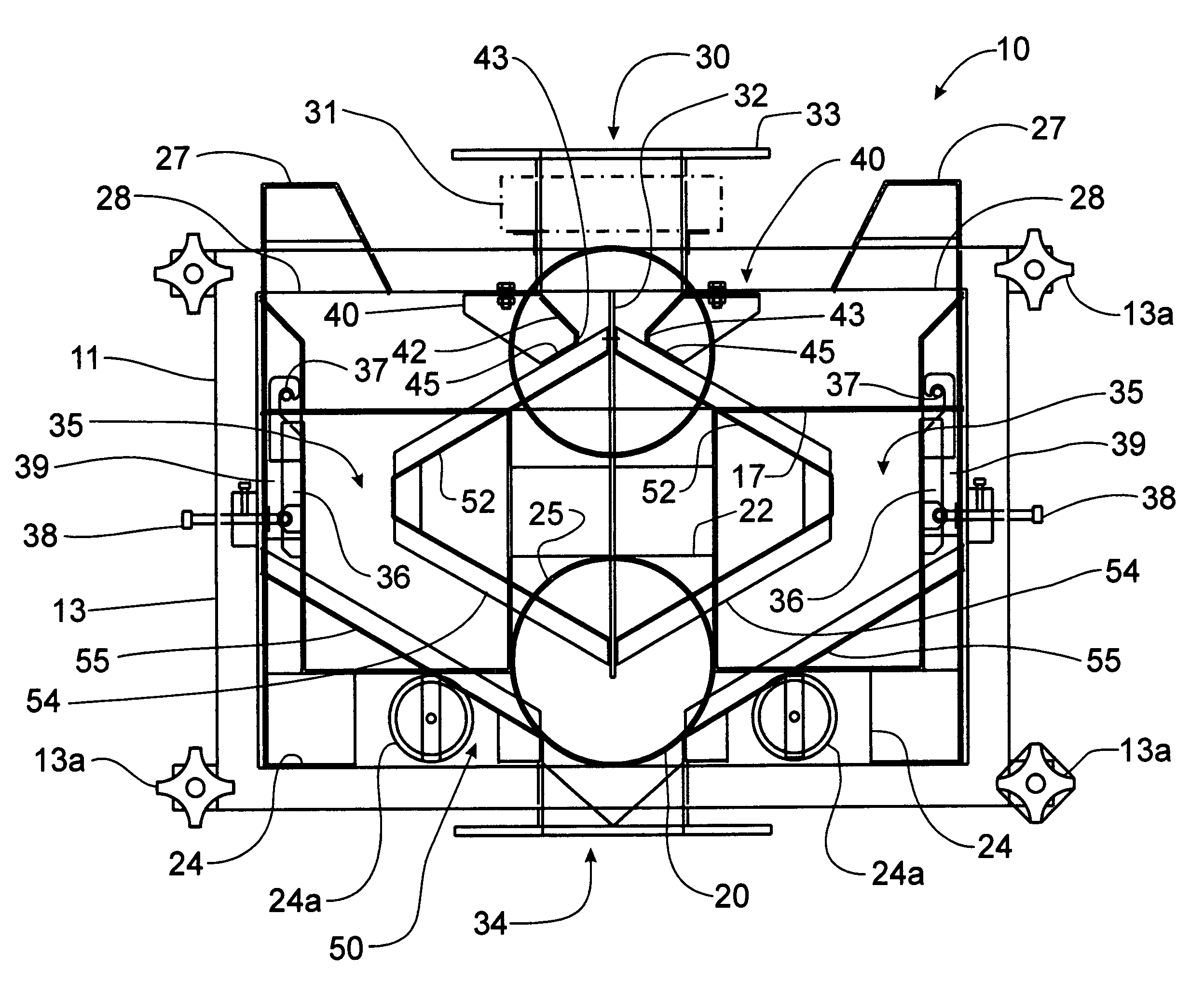
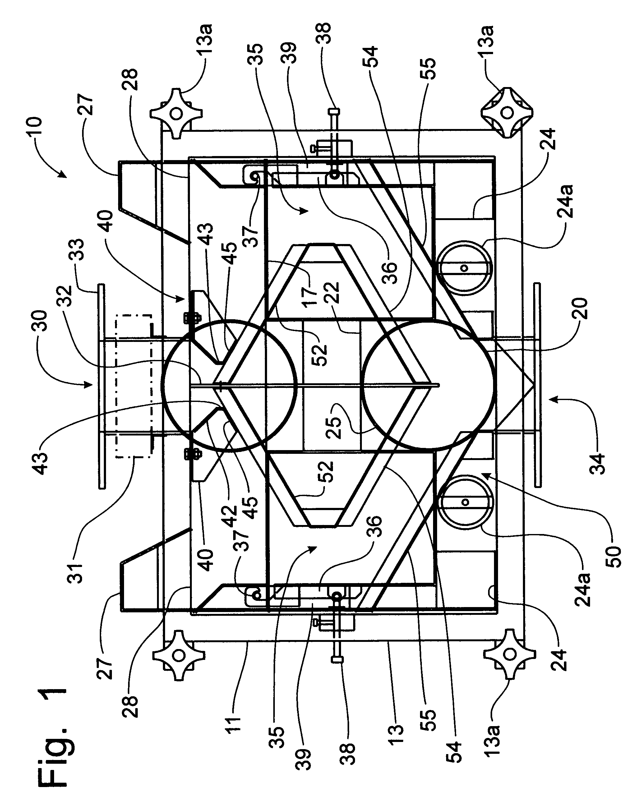
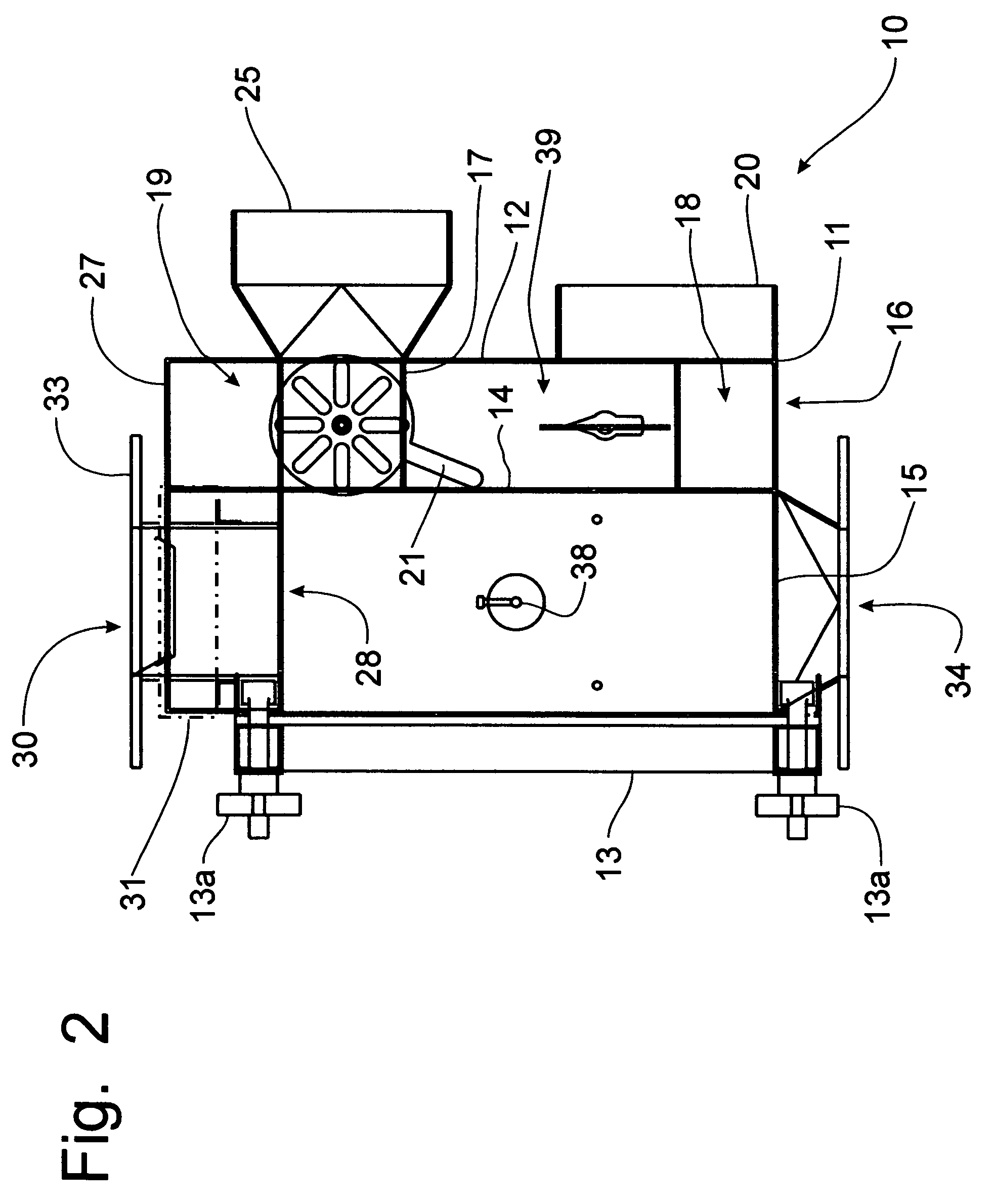
[0041]The dedusting apparatus is known in the art. A description of the structure and operation of a dedusting apparatus and a compact dedusting apparatus can be found in U.S. Pat. No. 5,035,331 and in U.S. Pat. No. 6,595,369, both of which were issued to Jerome I. Paulson, the contents of each of these patents being incorporated herein by reference. Typical particulate material to be cleaned by the dedusting apparatus 10 is plastic pellets that are to be passed into an injection molding machine to form plastic components. Examples of plastic particulate material that can be cleaned of contaminate material by the dedusting apparatus 10 are polyester, acrylic, high density polyethylene, polypropylene, nylon, polycarbonates, styrene, and low density polyethylene. Other types of particulate material that can be cleaned in the dedusting apparatus 10 include glass particles and grain.

[0042]Referring to FIGS. 1-9, the dedusting apparatus 10 is connected to a vertical portion of a fluent m...


PUM


Abstract

A compact housing for a dedusting apparatus utilizes a magnetic flux field to disrupt the static charge attracting dust particles to product particles, which along with fluidization and counter current airflow principles that are proven to dislodge dust particles from the product, provides a highly efficient, compact deduster. The housing supports a double wash deck with product flow separated between the back-to-back primary wash decks. A deflector directing the flow of product onto the primary wash decks is provided with an extension that extends parallel to the wash deck to eliminated product bouncing off of the wash deck. The lower air outlets are eliminated, while the upper air outlets are positioned in extensions to the main housing above the product inlet opening. Air flow through the Venturi zone is enhanced by re-directing clean air directly to the backside of the Venturi panels, thereby eliminating the extraneous by-pass boxes.

Description

FIELD OF THE INVENTION[0001]The invention disclosed in this application is directed generally to an apparatus for the cleaning and handling of particulate materials, such as plastic pellets, grains, glass, and the like, and particularly to the a low profile, compact apparatus that can be utilized in confined spaces without loss of efficiency.BACKGROUND OF THE INVENTION[0002]It is well known, particularly in the field of transporting and using particulate materials, commonly powders, granules, pellets, and the like, that it is important to keep product particles as free as possible of contaminants. Particulates are usually transported within a facility where they are to be mixed, packaged or used in a pressurized tubular system that in reality produces a stream of material that behaves somewhat like a fluid. As these materials move through the pipes, considerable friction is generated not only among the particles themselves, but also between the tube walls and the particles in the st...

Claims


Application Information

Patent Timeline
Patent Type & Authority Patents(United States)
IPC IPC(8): B07B4/02
CPCB07B7/00
Inventor PAULSON, JEROME I.SCHNEIDER, HEINZWAGNER, PAUL
Owner PELLETRON CORP
Why Eureka
Try Eureka