Single dielectric barrier aerodynamic plasma actuation

a technology of aerodynamic plasma and dielectric barrier, which is applied in the direction of automatic actuation, air-flow influencer, instruments, etc., can solve the problem of less tolerance of marginal flight conditions

Active Publication Date: 2008-06-03
UNIV OF NOTRE DAME DU LAC
View PDF27 Cites 140 Cited by
  • Summary
  • Abstract
  • Description
  • Claims
  • Application Information

AI Technical Summary

Benefits of technology

[0025]said energized electrical discharge supporting array generating a plasma directed momentum influenced improved pattern of lateral air flow across said aerodynamic vehicle component element airflow surface.

Problems solved by technology

The B-17 wing is or was of a large and long cross sectional shape and resulted in what was considered a tolerant and forgiving airfoil while the B-24 wing was considerably smaller yet capable of lifting a significantly larger aircraft payload but also was less tolerant of marginal flight conditions.

Method used


Image

  • Single dielectric barrier aerodynamic plasma actuation
  • Single dielectric barrier aerodynamic plasma actuation
  • Single dielectric barrier aerodynamic plasma actuation

Examples


Embodiment Construction

[0061]The following description refers to a list of some 21 published references that are identified in an included Appendix hereto and in an Information Disclosure Statement filed with the original application. These references are hereby incorporated by reference herein.

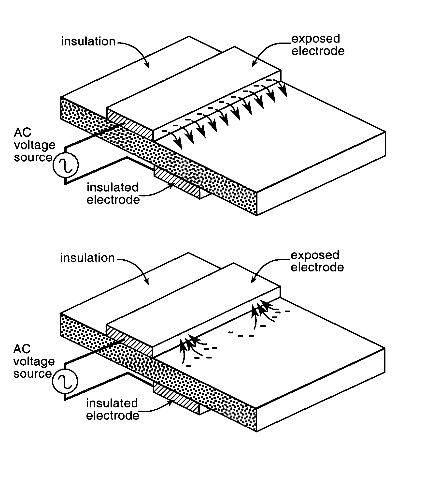
[0062]FIG. 6 in the drawings shows a cross sectional view of the salient parts of a “single dielectric barrier aerodynamic plasma actuator” in accordance with the present invention. In the FIG. 6 drawing an aerodynamic surface such as the metal sheet skin of for example an aircraft wing appears at 604 and a dielectric covering over this surface appears at 602. A pair of electrodes 600 and 606 is show to attend the dielectric covering 602 with one of these electrodes, 606, being exposed to the passing air stream as is represented at 608. The remaining one of the electrode pair, the electrode 600, is completely surrounded or encapsulated by the dielectric material 602 in the FIG. 6 apparatus. The electrode 600 may or...


PUM


Abstract

A single dielectric barrier aerodynamic plasma actuator apparatus based on the dielectric barrier discharge phenomenon is disclosed and suggested for application to aerodynamic uses for drag reduction, stall elimination and airfoil efficiency improvement. In the plasma actuator apparatus non-uniform in time and space, partially ionized gasses are generated by one or more electrode pairs each having one electrically encapsulated electrode and one air stream exposed electrode and energization by a high-voltage alternating current waveform. The influence of electrical waveform variation, electrode polarity, electrode size and electrode shape on the achieved plasma are considered along with theoretical verification of achieved results. Light output, generated thrust, ionizing current waveform and magnitude and other variables are considered. Misconceptions prevailing in the present day plasma generation art are addressed and are believed-to-be corrected. The influence of electrostatic shielding effects of the developed plasma on the applied electric field are also considered.

Description

CLAIM OF PRIORITY[0001]This application claims the benefit of U.S. Provisional Patent Application No. 60 / 520,787, filed Nov. 17, 2003. The contents of this provisional application are hereby incorporated by reference herein.RIGHTS OF THE GOVERNMENT[0002]The invention described herein may be manufactured and used by or for the Government of the United States for all governmental purposes without the payment of any royalty.BACKGROUND OF THE INVENTION[0003]Airfoils are found in many different shapes, sizes and functions in the aircraft and related arts. The Wright brothers, Orville and Wilbur, are for example known to have devoted extensive time to the achieving of a surprisingly efficient airfoil cross section for the propellers used on their early 1900's flyers. Airfoil shapes are of course also found in aircraft wing cross sections, in tail assemblies and in helicopter rotors as a short list of examples. Each of these airfoils involves a compromise between the achieved lift and drag...

Claims


Application Information

Patent Timeline
Patent Type & Authority Patents(United States)
IPC IPC(8): B64C13/02
CPCB64C23/005F05D2270/172Y02T50/166B64C2230/12Y02T50/10H05H1/2439
Inventor ENLOE, CARL L.MCLAUGHLIN, THOMAS E.JUMPER, ERIC J.CORKE, THOMAS C.
Owner UNIV OF NOTRE DAME DU LAC
Why Eureka
Try Eureka