
Optical transceiver for 100 gigabit/second transmission

a transceiver and optical technology, applied in the field of optical transceivers, can solve the problems of limited applications of such cabling, and achieve the effect of high speed

Active Publication Date: 2008-06-03
NEOPHOTONICS CORP
View PDF1 Cites 44 Cited by
  • Summary
  • Abstract
  • Description
  • Claims
  • Application Information

AI Technical Summary

Benefits of technology

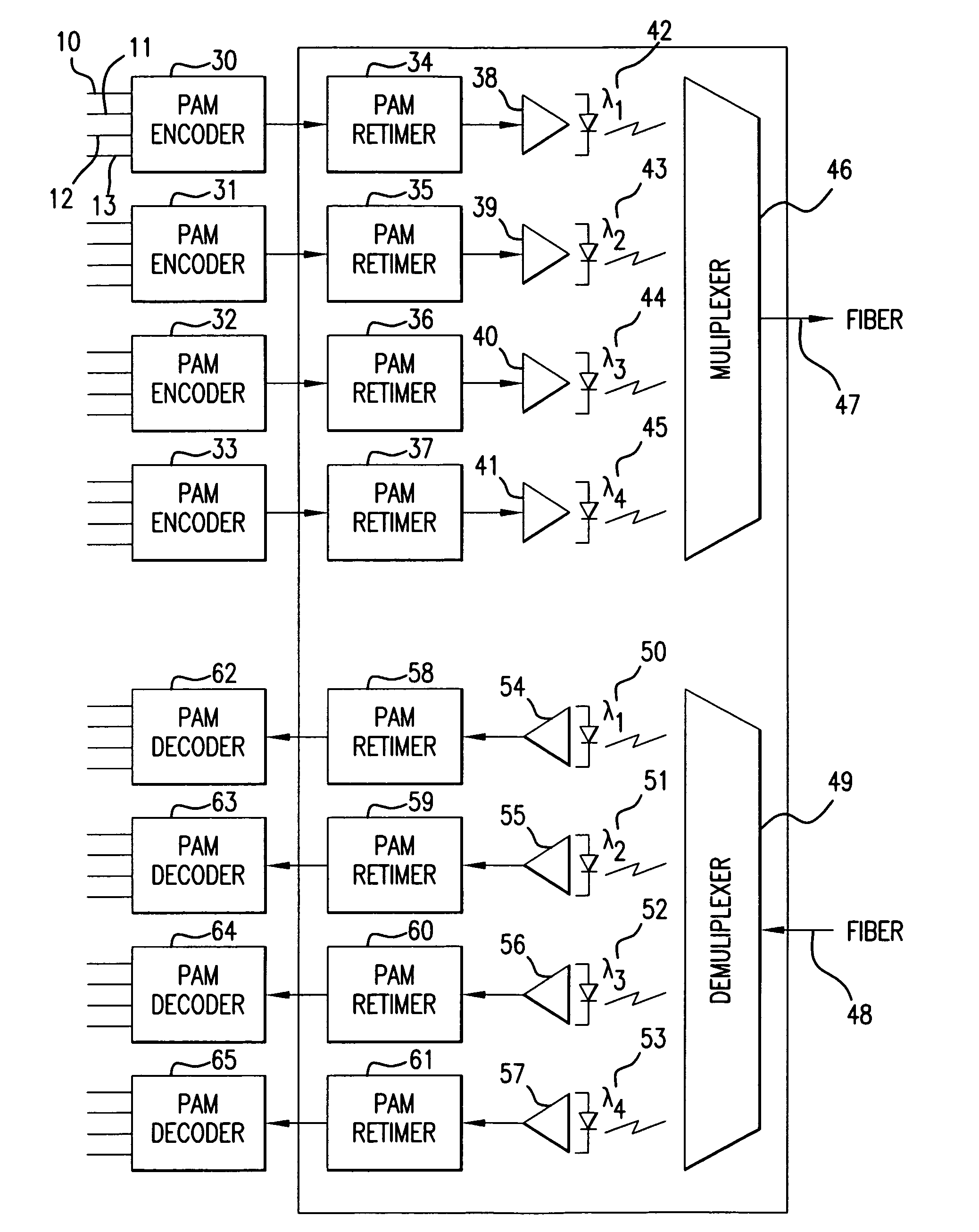
The present invention provides a high-speed optical transceiver that can transmit information at a speed of at least 100 Gbps in a small, standardized form. It is suitable for both short-range and long-haul applications using optical wavelength division multiplexed transmission. The optical transceiver includes a modulator for converting electrical signals to pulse amplitude modulated signals, a signal timing circuit for aligning data signals, an electro-optical subassembly for converting electrical signals to optical signals, and a multiplexer for transmitting multiple optical beams over an optical fiber. The invention also provides an optical transceiver for use in an optical wavelength division multiplexed transmission system with a signal timing circuit connected to each lane in a wavelength division multiplexed system.

Problems solved by technology

WDM high date rate applications have found widespread application in short reach Ethernet networks The difficulties associated with multi-gigabit signaling over existing wiring has limited the applications for such cabling, although efforts are currently underway for new copper cabling standards.

Method used


Image

  • Optical transceiver for 100 gigabit/second transmission
  • Optical transceiver for 100 gigabit/second transmission
  • Optical transceiver for 100 gigabit/second transmission

Examples


Embodiment Construction

[0045]Details of the present invention will now be described, including exemplary aspects and embodiments thereof. Referring to the drawings and the following description, like reference numbers are used to identify like or functionally similar elements, and are intended to illustrate major features of exemplary embodiments in a highly simplified diagrammatic manner. Moreover, the drawings are not intended to depict every feature of actual embodiments or the relative dimensions of the depicted elements, and are not drawn to scale.

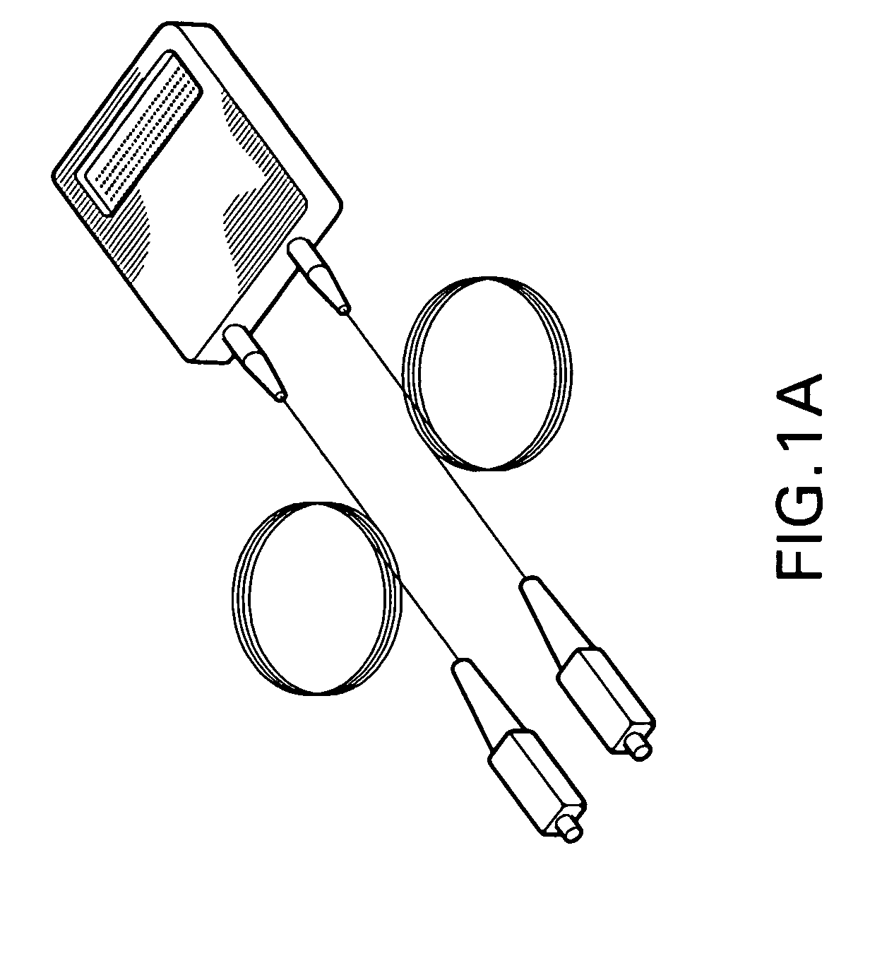
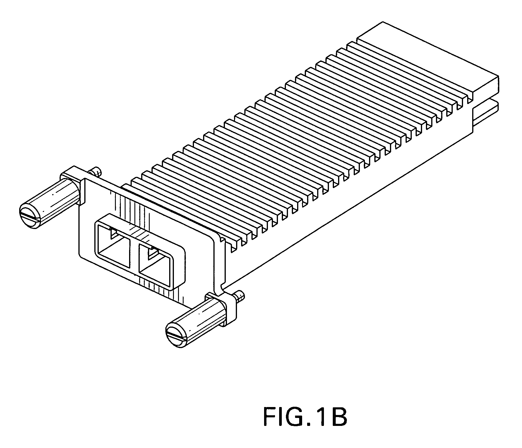
[0046]FIG. 1A and FIG. 1B are perspective views of an optical transceiver module 100 in which an exemplary embodiment in accordance with aspects of the present invention may be implemented. In particular, FIG. 1A depicts the 300-pin form factor, and FIG. 1B depicts the XENPAK type form factor.

[0047]In this particular embodiment, the module 100 is similar to the IEEE 802.3ae 10GBASE-LX4 Physical Media Dependent sub-layer (PMD) by having the same laser freque...


PUM


Abstract

An optical transmitter for converting and coupling an information-containing electrical signal with an optical fiber having an electrical input for coupling with an external electrical cable or information system device having a plurality of parallel data lines, a modulator for converting between an information-containing electrical signal on each data line and a multi-level digital pulse amplitude modulated signal corresponding to the binary electrical signal; and a signal timing circuit coupled to said modulator for aligning the data signal to a predetermined clock signal. The transmitter is preferably wavelength division multiplexed, using an electro-optical subassembly coupled to each respective timer circuit for converting between the information-containing electrical signal and a modulated optical signal corresponding to the electrical signal at a predetermined wavelength. The transceiver is preferably implemented in a pluggable standardized form factor.

Description

REFERENCE TO RELATED APPLICATIONS[0001]This application is related to co-pending U.S. patent application Ser. No. 10 / 866,265 filed Jun. 14, 2004, assigned to the common assignee.[0002]This application is also related to co-pending U.S. patent application Ser. No. 11 / 212,822 filed Aug. 25, 2005, assigned to the common assignee.BACKGROUND OF THE INVENTION[0003]1. Field of the Invention[0004]The invention relates to optical transceivers, and in particular to optical signal modulation techniques that provide a communications link between computers or communications units over optical fibers, such as used in high throughput fiber optic communications links in local and wide area networks and storage area networks.[0005]2. Description of the Related Art[0006]Communications networks have experienced dramatic growth in data transmission traffic in recent years due to worldwide Internet access, e-mail, and e-commerce. As Internet usage grows to include transmission of larger data files, incl...

Claims


Application Information

Patent Timeline
Patent Type & Authority Patents(United States)
IPC IPC(8): G02B6/36H04B10/00H04J14/00
CPCH04B10/40H04B10/504H04J14/02H04L7/00H04J14/0307
Inventor DALLESASSE, JOHN
Owner NEOPHOTONICS CORP
Learn More