Fan motor

a technology of fan motor and blade, which is applied in the direction of marine propulsion, vessel construction, and other chemical processes, can solve the problems of reduced effect of above structures, and reduced number of sawtoothed teeth, so as to reduce the noise of aerodynamics, improve ventilation efficiency, and manufacture inexpensively

Inactive Publication Date: 2008-06-03
SONY CORP
View PDF15 Cites 23 Cited by
  • Summary
  • Abstract
  • Description
  • Claims
  • Application Information

AI Technical Summary

Benefits of technology

[0008]In the fan motor having a small thickness, however, since it is difficult to have a sufficient impeller width in an axial direction, the number of teeth of the sawtoothed structure to be formed at edge ends of the inner and outer peripheries of the blade or the number of the annular plates to be stacked at the outer periphery of the impeller with a predetermined pitch decreases. Therefore, the effect of the above structures is limited. In addition, to form the sawtooth structure (a structure of a plurality of teeth, or protruding and recessed portions) at the inner and outer peripheries of the blade edge ends in the axial direction, a die for molding an impeller having such blades will have a complicated structure such as a slide-type die (a multi-divided die) and the like. Such die structure strictly requires diameter accuracy and thermal management for die fitting, thus resulting in an increased cost of fabricating the die. In addition, in the method of stacking annular plates, the number of component parts and manufacturing process steps will be increased, thus also resulting in increased product cost.
[0009]The present invention has been conceived to address the above-mentioned issues and aims at providing a fan motor having a small thickness that enables the reduction of aerodynamic noises and improves the ventilation efficiency by forming a tooth structure (a structure of a plurality of teeth or protruding and recessed portions) or chamfers at the edge end of its blade in a diametrical direction, the length of the blade in a diametrical direction being made longer than the width in an axial direction. Further, the blade of the fan motor in the present invention may be formed by an easy process.
[0011]As described above, the present invention provides the fan motor having a small thickness and its impeller blades formed such that the length in the diametrical direction is longer than the width in the axial direction. Since the blade has the tooth structure or chamfers at its edge end in the diametral direction, which is longer than the width in the axial direction, the trailing vortex is suppressed and the aerodynamic noises are reduced, and the ventilation efficiency is improved as compared to a blade in the related art, which has a tooth structure at the edge end in the axial direction. Therefore it is possible to make a fan motor of similar functionality smaller and thinner.
[0012]Further, an impeller of a fan motor is normally fabricated with a resin molding; however, the tooth structure or chamfers are formed at the edge end portion of the blade in the diametrical direction according to the present invention, and a general up and down mold structure can be used to fabricate this impeller. As a result, the impeller may be manufactured inexpensively because the cost of the die can be reduced and extra manufacturing processes are not necessary.

Problems solved by technology

In the fan motor having a small thickness, however, since it is difficult to have a sufficient impeller width in an axial direction, the number of teeth of the sawtoothed structure to be formed at edge ends of the inner and outer peripheries of the blade or the number of the annular plates to be stacked at the outer periphery of the impeller with a predetermined pitch decreases.
Therefore, the effect of the above structures is limited.
Such die structure strictly requires diameter accuracy and thermal management for die fitting, thus resulting in an increased cost of fabricating the die.
In addition, in the method of stacking annular plates, the number of component parts and manufacturing process steps will be increased, thus also resulting in increased product cost.

Method used


Image

  • Fan motor
  • Fan motor
  • Fan motor

Examples


first embodiment

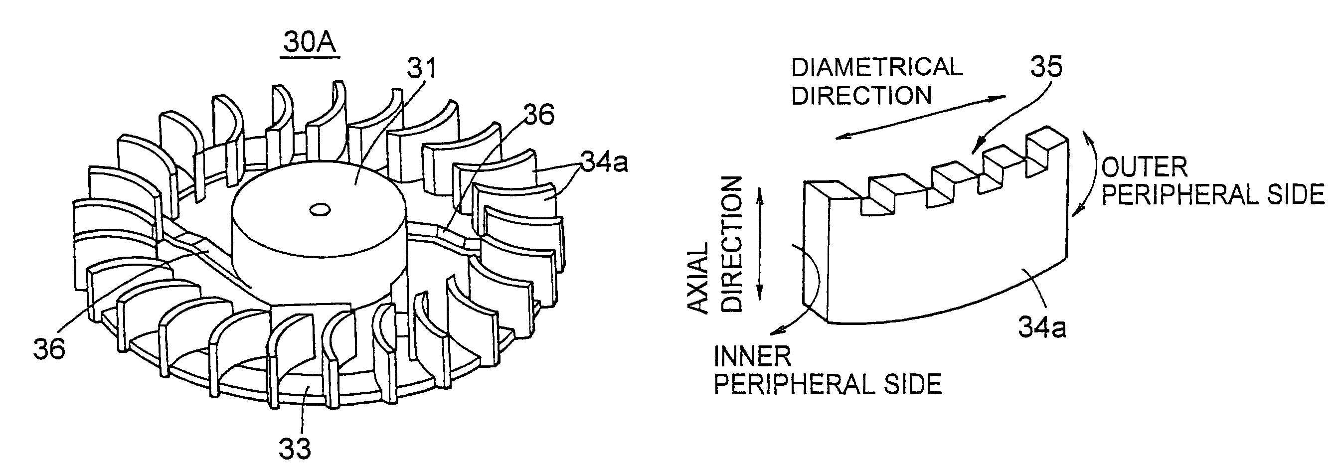
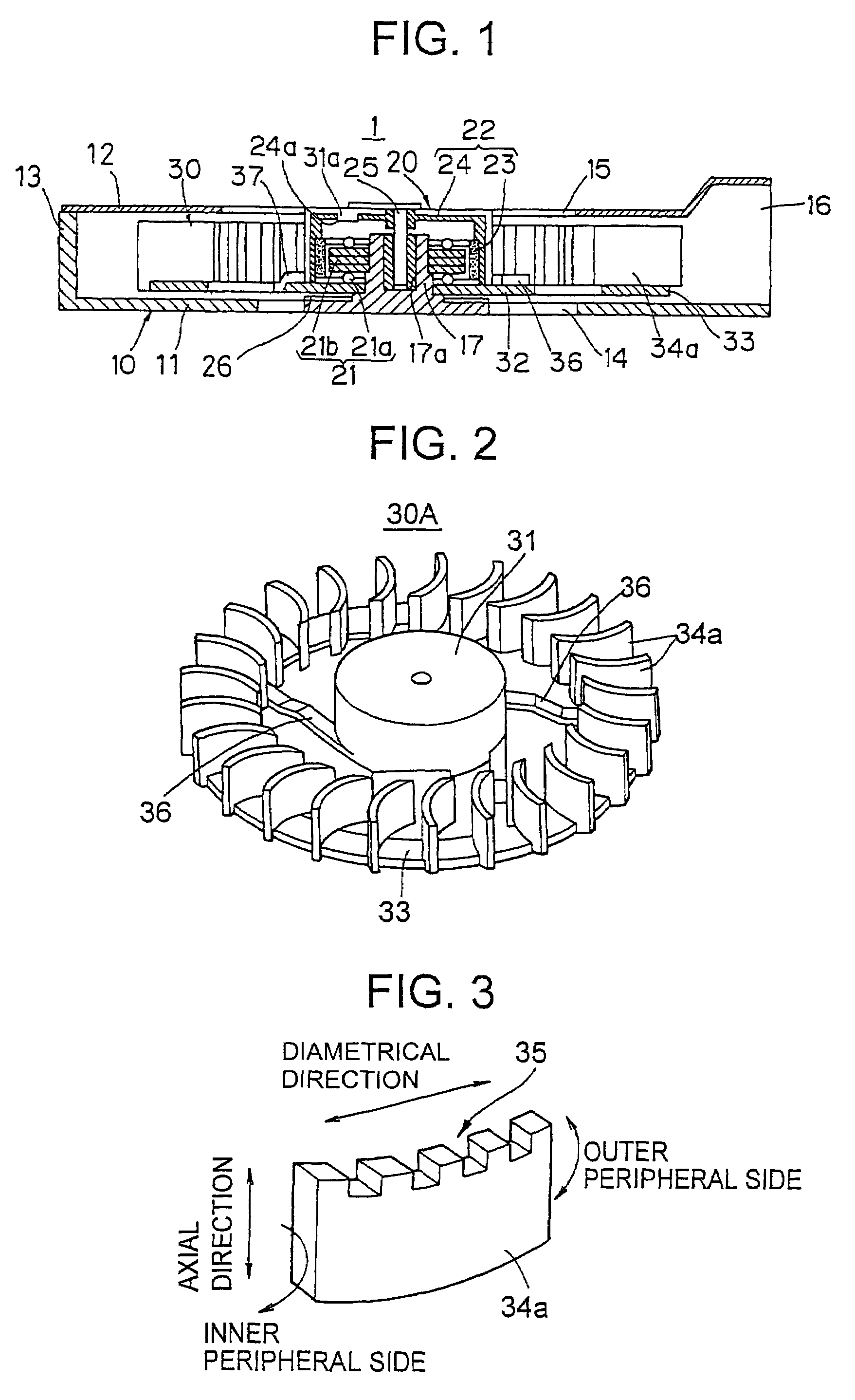
[0026]FIG. 1 shows a cross-sectional view of a fan motor according to an embodiment of the present invention; FIG. 2 shows an impeller of a fan motor; and FIG. 3 shows a configuration example of a blade of an impeller. Fan motor 1 is constituted by a flat-shaped housing 10, a motor 20 of an outer rotor type provided within the housing 10, and a resin impeller 30A integrally rotating with the rotor.

[0027]The housing 10 has inlets 14 and 15 on a lower wall 11 and an upper wall 12, respectively, which are connected to an inside of a blade 34a of the impeller 30A, and a blowport 16 on the one side of a side wall 13. In addition, in the central part of the lower wall 11, a hub section 17 having an aperture 17a is formed, which supports a stator 21 of the motor 20 and a rotating shaft 25 of a rotor 22.

[0028]The motor 20 is configured by an inner stator 21 constituted of a winding 21a and a core 21b, an outer rotor 22 constituted of a magnet 23 and a rotor case 24, a rotating shaft 25 prov...

second embodiment

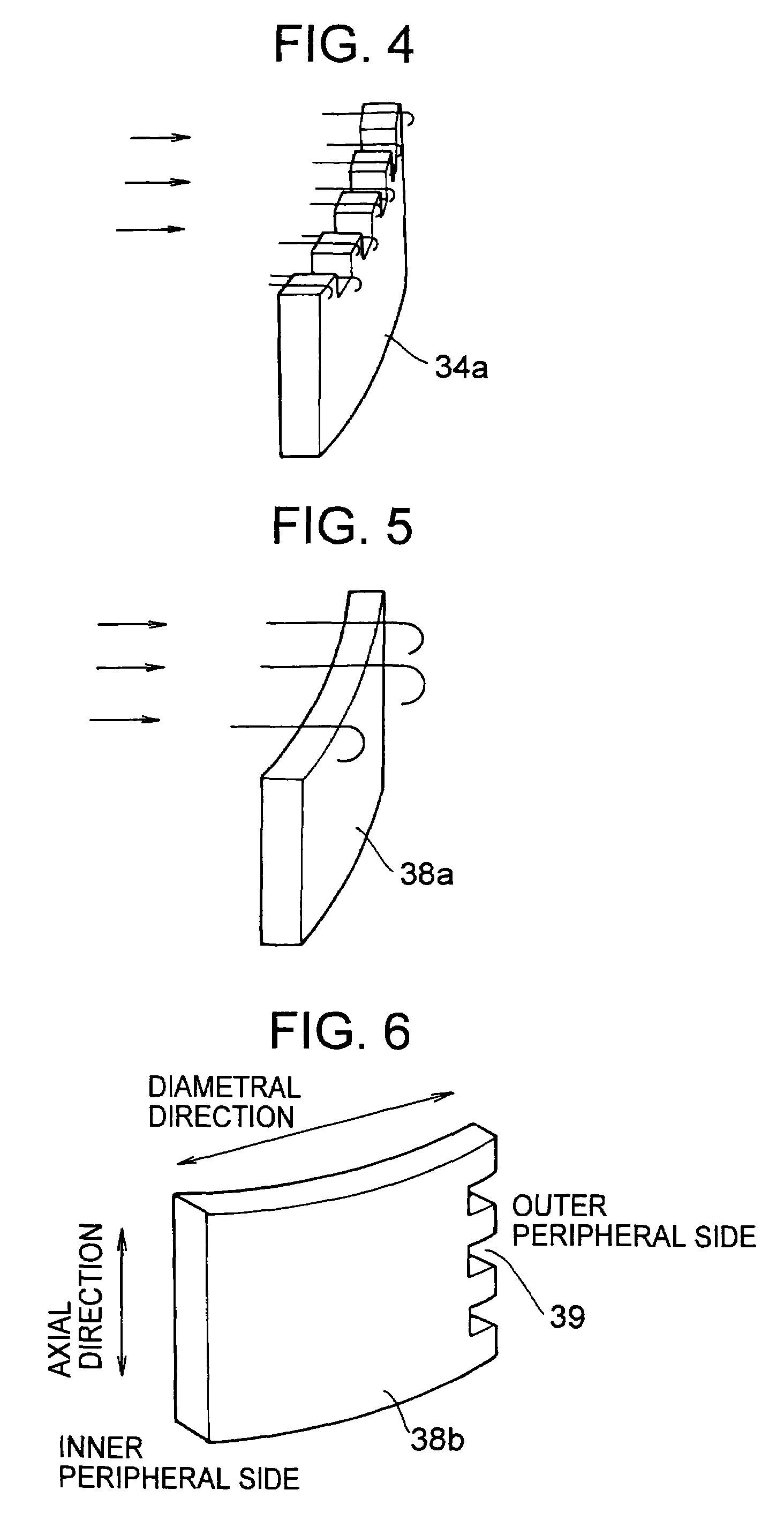
[0039]FIG. 9 shows an impeller of a fan motor according to a second embodiment. The impeller 30B is configured by a hub section 31 formed so as to cover a rotor case 24 of a motor 20 (FIG. 1) and a plurality of blade sections 37 integrally formed with the hub section 31. The blade section 37 is constituted by blades 34c and an arm part 37a supporting the blades 34c. A length (width) of the arm part 37a in an axial direction is formed shorter than a length of the blade 34c in a diametrical direction in order to have enough space between inner surfaces of a lower wall 11 and of an upper wall 12 of a housing 10 (FIG. 1). The blade 34c is formed, as shown in FIG. 10, to have four pairs of the tooth structure 35 at its upper and lower edge ends in the diametrical direction.

[0040]Since the tooth structures are respectively provided at the upper and lower edge ends of the blade 34c in the diametrical direction, the turbulence is forcibly induced in the trailing vortex air flow generated at...

application example

[0042]In FIG. 12, a cooling module utilizing the fan motor according to the present invention is shown. In the figure, reference numeral 41 indicates a heat spreader of a module, which generates the heat largely (for example, a CPU), mounted on a notebook personal computer, reference numeral 42 is a plate-shaped heat pipe provided to the heat spreader, reference numeral 43 is a heat sink constituted by a plurality of heat dissipating fins provided to an upper surface of the heat pipe 42 on the waste-heat side, and reference numeral 1 is the fan motor according to the present invention, which has the impeller whose blade is formed to have the tooth structure or the chamfers at the edge end in the diametrical direction.

[0043]A blowport for sending air to the heat sink 43 in the housing 10 of the fan motor 1 is formed widely in order to send air toward a whole rear-end portion of the heat sink 43, and is provided on the heat pipe 42 so as to contact the rear-end portion of the heat sin...


PUM


Abstract

A fan motor having a small thickness and its impeller's blades formed to have a longer length in the diametrical direction than a width in the axial direction. Since the blade of the fan motor has a tooth structure or chamfers at its edge end in the diametrical direction, turbulence is forcibly evoked in an airflow to promote the turbulent diffusion, thereby suppressing the trailing vortex and reducing the aerodynamic noises, and thus the ventilation efficiency is improved.

Description

CROSS REFERENCE TO RELATED APPLICATION[0001]The present document is based on Japanese Priority Document JP2003-150009, filed in the Japanese Patent Office on May 28, 2003, the entire contents of which are incorporated herein by reference to the extent permitted by law.BACKGROUND OF THE INVENTION[0002]1. Field of the Invention[0003]The present invention relates to a fan motor having a small thickness and its blades formed to have a tooth structure or chamfers at the edge ends.[0004]2. Description of the Related Art[0005]As notebook PCs and other apparatuses have become increasingly thinner, they are expected to become much thinner in the future. Accordingly, cooling devices that will be used in notebook PCs, such as fan motors, will also be required to be much thinner. However, as notebook PCs become thinner, the temperature inside the housing increases and the ventilation efficiency decreases as the width of blades for dissipation of heat to the outside becomes narrow. As a possible...

Claims


Application Information

Patent Timeline
Patent Type & Authority Patents(United States)
IPC IPC(8): F04D29/30F04D29/38F04D29/28F04D29/66
CPCF04D29/282F04D29/30F04D29/384F04D29/388F04D29/663F04D29/667F05D2210/12Y10S415/00Y10S416/00Y10S417/00
Inventor KANEKO, SACHIKOSHISHIDO, YUJIHASHIMOTO, TOSHIOKIMURA, TOORU
Owner SONY CORP
Why Eureka
Try Eureka