Control unit for electric power steering apparatus

a technology for controlling units and electric power steering devices, which is applied in the direction of analogue-digital converters, anti-hunting elements, and element comparison. it can solve the problems of a lot of hardware, and a lot of processing tim

Active Publication Date: 2008-06-03
NSK LTD +1
View PDF16 Cites 15 Cited by
  • Summary
  • Abstract
  • Description
  • Claims
  • Application Information

AI Technical Summary

Problems solved by technology

However, since the performance of detecting the abnormality is definite and is not sufficient, there is a case that a unique abnormality detecting circuit explained below is provided.
However, whichever method is executed, it is necessary to execute an AD conversion of the sin signal and the cos signal in synchronous with the carrier wave, an interruption by a carrier wave peak timing, a calculation of (sin θ)2+(cos θ)2 and the like, and the calculation requires a lot of processing time.
Further, in the case of processing by a software, there is a problem the process is a burden to the CPU, and in the case of processing by a hardware, there is a problem that a lot of hardwares are necessary.
For example, the control afler detecting the failure of the motor angle detecting device corresponding to one of the sensors is a very important problem for a safety steering of the vehicle, and various control unit have been conventionally considered.
However, if an assist of the handle operation by the electric power steering apparatus is lost, and the operation is changed suddenly to the manual operation, a great uncomfortable feeling is applied to the handle operation.
As mentioned above, in the control in the case of detecting the abnormality of the rotation angle θ, there is a problem that the control or the electric power steering apparatus can not be continued in accordance with the position of the rotation angle θ at a time of detecting the abnormality, and the duration is widely limited.
Further, the load applied to the driver undesirably becomes greater in the manual operation in correspondence to the increase in size of the vehicle mounting the electric power steering apparatus thereon in recent years.

Method used


Image

  • Control unit for electric power steering apparatus
  • Control unit for electric power steering apparatus
  • Control unit for electric power steering apparatus

Examples


first embodiment

[0056]A description will be given first of an embodiment in the case that the present invention is processed by a software.

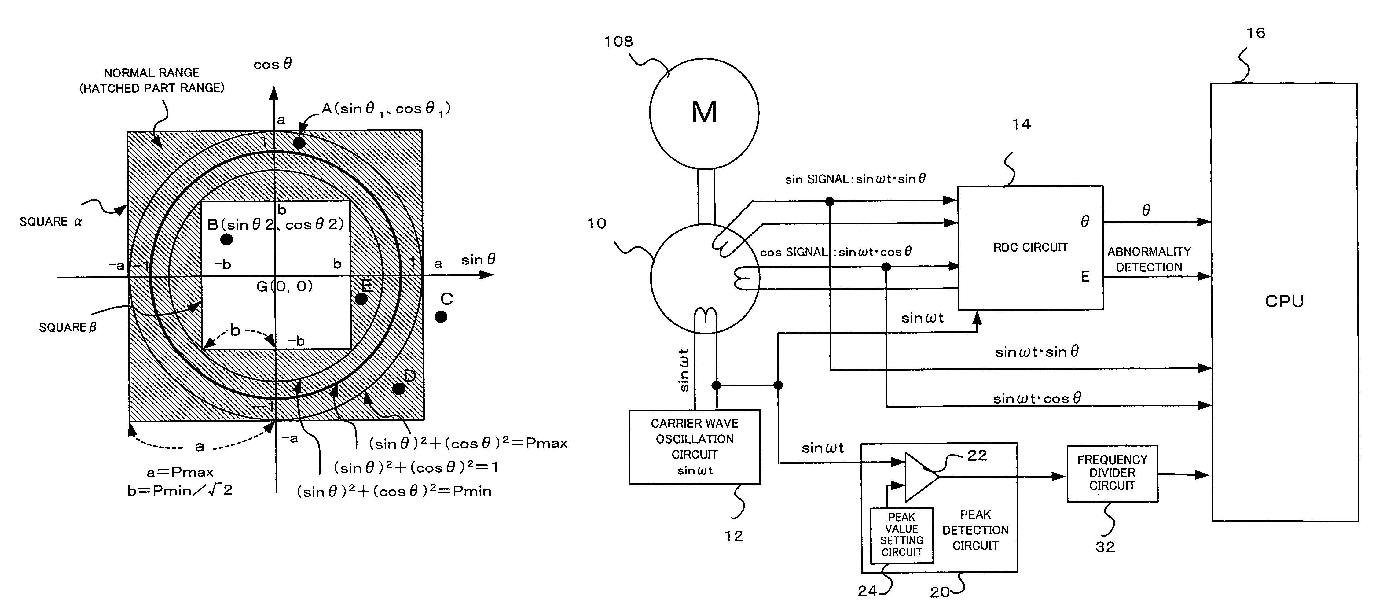
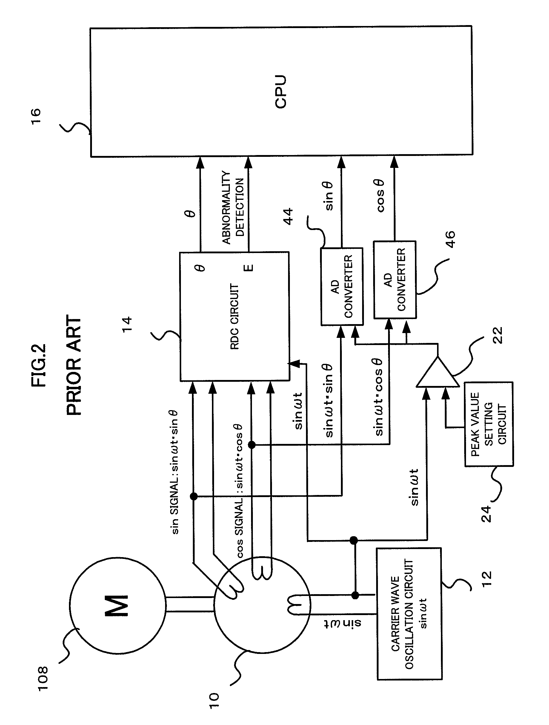
[0057]In FIG. 7, a sin signal (sin ωt·sin θ) and a cos signal (sin ωt·cos θ) output from an angular resolver 10 are input to a CPU circuit 16 via AD converter (not shown). In this case, a carrier wave signal sin ωt output from a carrier wave oscillation circuit 12 is not directly input to the CPU circuit 16, but is input to a peak detection circuit 20 so as to detect a peak time of the carrier wave sin ωt. In specific, the carrier wave signal sin ωt is input to the peak detection circuit 20, a peak value of the carrier wave signal sin ωt shown by a peak value setting circuit 24 and the carrier wave are compared by a comparator circuit 22, and the peak time is detected on the basis of the compared result. A frequency divider circuit 32 arranged between the peak detection circuit 22 and the CPU circuit 16 inputs the peak time of the carrier wave to the CPU circuit...

second embodiment

[0064]A description will be given of a second embodiment in accordance with the hardware process with reference to FIGS. 10 and 11. As shown in FIG. 10, an abnormality judging circuit 18 is arranged in a front stage to which the sin signal, the cos signal and the carrier wave signal are input to the CPU 16, and the result obtained by judging whether the sin signal and the cos signal are normal or abnormal is input to the CPU 16 after judging whether the sin signal and the cos signal are normal or abnormal.

[0065]A description will be given of a structure and an operation of the abnormality judging circuit 18 with reference to FIG. 11. The carrier wave signal sin ωt is input to the peak detection circuit 20, the peak value of the carrier wave signal sin ωt shown by the peak value setting circuit 24 and the carrier wave are compared in the comparator circuit 22, and the peak time is detected on the basis of the compared result. In FIG. 11, the frequency divider circuit 32 is connected ...

third embodiment

[0093]A description will be given of a preferable embodiment in accordance with the present invention with reference to FIG. 14 showing in correspondence to FIG. 5, on the basis of the theory of the present invention described above. FIG. 14 is a block diagram showing an entire of a control unit for electric power steering apparatus including an angle processing circuit 50 in accordance with the present invention, and FIG. 15 is a block diagram showing details of the angle processing circuit 50 by actualizing the angle processing circuit 50 by a hardware.

[0094]The embodiment in FIG. 14 is structured by a vector control portion (a portion surrounded by a broken line A) used in a normal control, and a rectangular wave control (a portion surrounded by a broken line B) used in an abnormal matter in the case that the angular resolver or the resolver digital conversion circuit becomes abnormal. Since a resolver digital conversion circuit 311 is generally provided with an earth terminal co...


PUM


Abstract

Since an abnormality is judged by executing a square calculating process with respect to sin θ and cos θ for detecting an abnormality in an angular resolver, a processing time is elongated, and a burden to a CPU is great. Since the invention prepares a map which can judge whether the combination of sin θ and cos θ is normal or abnormal, and judges by mapping the combination of the detected sin θ and cos θ, a process can be easily executed, a processing speed is high, and a burden to the CPU can be reduced. Further, an assist can be maintained by controlling a motor by a rectangular wave current by detecting a rotation angle signal at low resolution level, such as Hall sensors arranged around the motor.

Description

TECHNICAL FIELD[0001]The present invention relates to a control unit for electric power steering apparatus, and more particularly to a control unit for electric power steering apparatus which is provided with an abnormality detecting function of an angle detecting device of a motor used in the electric power steering apparatus, and takes into consideration a protecting operation with respect to a failure of the angle detecting device.BACKGROUND ART[0002]An electric power steering apparatus for applying a steering assist force to a steering mechanism of an automobile by a rotating force of a motor transmits a driving force of the motor by a transmitting mechanism such as a gear or a belt through a reduction gear to apply the steering assist force to a steering shaft or a rack shaft. An example of a brief structure of such an electric power steering apparatus is shown in FIG. 1 and will be described.[0003]A shaft 102 of a steering wheel 101 is coupled to tie rods 106 of steered wheels...

Claims


Application Information

Patent Timeline
Patent Type & Authority Patents(United States)
IPC IPC(8): H03M1/48B62D5/04G01D5/244G01D5/245
CPCB62D5/046B62D5/0487G01D5/24461H02P29/022H02P29/032G01D3/08
Inventor OTSUKA, TETSUROHORIKOSHI, ATSUSHIAOKI, YUHO
Owner NSK LTD
Why Eureka
Try Eureka