
Polarizable electrode member, process for producing the same, and electrochemical capacitor utilizing the member

a technology of polarized electrodes and electrode parts, applied in the field of electrochemical capacitors, can solve the problems of insufficient strength of aluminum foil, difficult to thin aluminum foil, etching and roughening of aluminum foil, etc., to suppress internal resistance and deterioration of electrical capacitance, improve energy density and power density, and reduce the effect of etching and roughening

Active Publication Date: 2008-06-03
PANASONIC CORP
View PDF8 Cites 13 Cited by
  • Summary
  • Abstract
  • Description
  • Claims
  • Application Information

AI Technical Summary

Benefits of technology

The solution results in higher energy and power density with lower internal resistance, improved reliability, and increased productivity at reduced costs, as demonstrated by the electrochemical capacitor's performance in continuous voltage tests.

Problems solved by technology

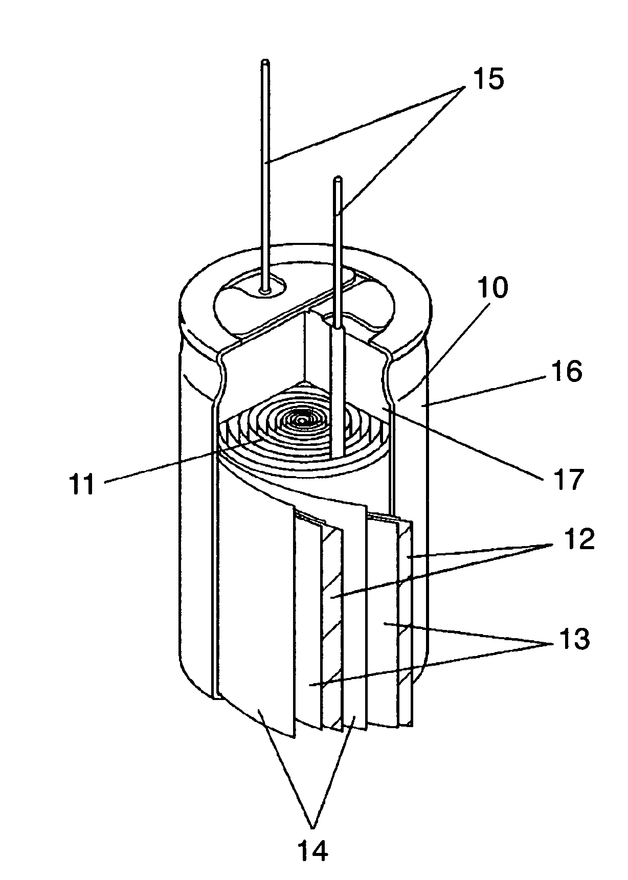
However, the surface-etched and roughened aluminum foil has a problem; that is, strength of the foil is not high enough to withstand a tension it could encounter during manufacturing stage, sometimes it is broken during manufacturing.
Thus, it is not easy to make the foil thinner.
So, a contact area between electrode layer and current collector decreases and the coupling strength deteriorates.
As the result, the internal resistance increases and the reliability deteriorates with an electrochemical capacitor.
Furthermore, it is difficult in the conventional capacitors to form an electrode layer directly on anchor coat layer 18.
An additional step for manufacturing electrode sheet 13 brings about a lowered productivity, generating a serious cost issue.

Method used


Image

  • Polarizable electrode member, process for producing the same, and electrochemical capacitor utilizing the member
  • Polarizable electrode member, process for producing the same, and electrochemical capacitor utilizing the member
  • Polarizable electrode member, process for producing the same, and electrochemical capacitor utilizing the member

Examples


Embodiment Construction

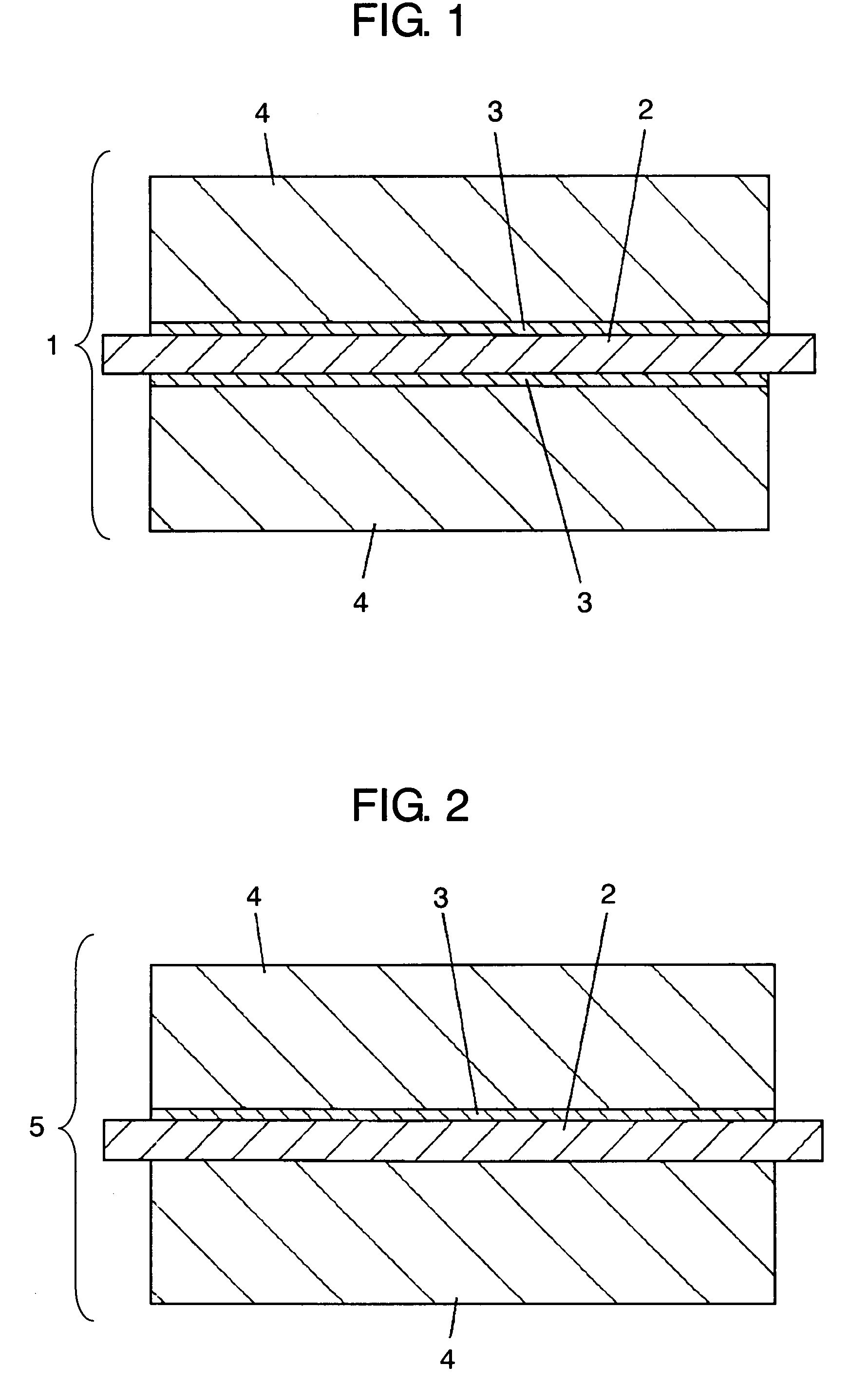
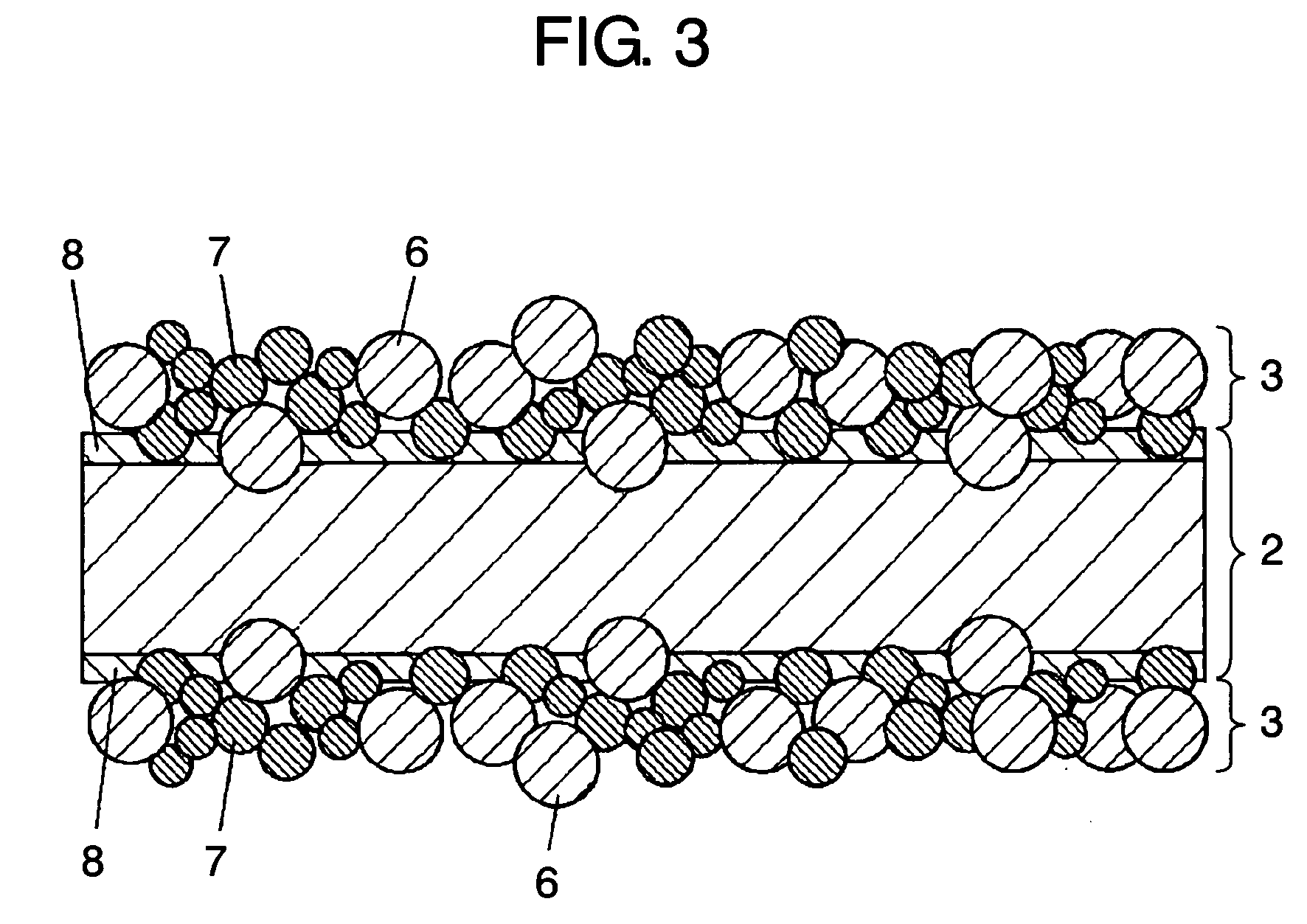
[0037]A polarized electrode in the present invention is formed of a plain foil used for current collector and an anchor coat layer which has conductivity and an adhesive property disposed between the current collector and an electrode layer. This structure makes it possible to form the electrode in a thinner configuration and to provide the electrode layer directly on the anchor coat layer. Furthermore, since a sufficient coupling strength is insured between the current collector and the electrode layer, it can suppress an increase of the internal resistance and a deterioration of electrical capacitance realizing an increased energy density and power density. Still further, the use of a graphitized carbon black as conductive carbon in providing the anchor coat layer contributes to the lower resistance.

[0038]In the following, the present invention is described using an exemplary embodiment.

Exemplary Embodiment

[0039]FIG. 1 is a cross sectional view used to describe the structure of a ...


PUM

PropertyMeasurementUnit
particle diameteraaaaaaaaaa
electric conductivityaaaaaaaaaa
intruding depthaaaaaaaaaa

Abstract

A polarized electrode for use in an electrochemical capacitor, in which electrode includes a current collector made of a metal plain foil, an anchor coat layer formed at least on one of the surfaces of the current collector, and an electrode layer formed on either the anchor coat layer or the current collector. The anchor coat layer contains a conductive carbon and a binder. The conductive carbon is graphitized carbon black. The binder contains at least one selected from the group consisting of an ammonium salt of carboxymethylcellulose, a rubber polymer, polytetrafluoroethylene, polyvinyl alcohol, polyvinyl pyrrolidone, alternating copolymer of isobutylene-maleic anhydride. With this configuration, a polarized electrode can be made thinner, and an electrode layer can be formed directly on the anchor coat layer. Furthermore, it can ensure sufficient coupling strength between the current collector and the electrode layer, and increase the energy density and the power density realizing a reduced resistance.

Description

RELATED APPLICATIONS[0001]This application is the U.S. National Phase under 35 U.S.C. § 371 of International Application No. PCT / JP2005 / 023113, filed on Dec. 16, 2005, which in turn claims the benefit of Japanese Application No. 2004-376038, filed on Dec. 27, 2004, and Japanese Application No. 2005-114141, filed on Apr. 12, 2005, the disclosures of which Applications are incorporated by reference herein.TECHNICAL FIELD[0002]The present invention relates to an electrochemical capacitor for various kinds of electronic apparatus, and a polarized electrode used in the electrochemical capacitor. A method for manufacturing the polarized electrode is also offered.BACKGROUND ART[0003]A capacitor which contains a conventional polarized electrode is described in, for example, Japanese Patent Unexamined Publication No. H11-154630, Japanese Patent Unexamined Publication No. 2004-186266, etc.[0004]The structure of a conventional electrochemical capacitor 10 is described referring to FIG. 6. Capa...

Claims


Application Information

Patent Timeline
Patent Type & Authority Patents(United States)
IPC IPC(8): H01G9/00H01G11/26H01G11/28H01G11/38
CPCH01G11/38H01G11/26H01G11/28Y02E60/13Y02T10/7022Y02T10/70
Inventor SAKATA, MOTOHIROSHIMASAKI, YUKIHIRO
Owner PANASONIC CORP
Learn More