Medical electrical lead providing far-field signal attenuation

a technology of far-field signal and medical electrical leads, which is applied in the direction of transvascular endocardial electrodes, internal electrodes, therapy, etc., can solve the problems of inability to suppress or attenuate the voltage level of far-field electrical signals, unable to achieve the effect of enhancing inhibition, optimizing the pacing and sensing performance of leads, and inhibiting fibrotic encapsulation

a technology of far-field signal and medical electrical leads, which is applied in the direction of transvascular endocardial electrodes, internal electrodes, therapy, etc., can solve the problems of inability to suppress or attenuate the voltage level of far-field electrical signals, unable to achieve the effect of enhancing inhibition, optimizing the pacing and sensing performance of leads, and inhibiting fibrotic encapsulation

US7383091B1Active Publication Date: 2008-06-03PACESETTER INC

Image

  • Medical electrical lead providing far-field signal attenuation
  • Medical electrical lead providing far-field signal attenuation
  • Medical electrical lead providing far-field signal attenuation

Examples


Embodiment Construction

[0026]The following description presents preferred embodiments of the invention representing the best mode contemplated for practicing the invention. This description is not to be taken in a limiting sense but is made merely for the purpose of describing the general principles of the invention whose scope is defined by the appended claims.

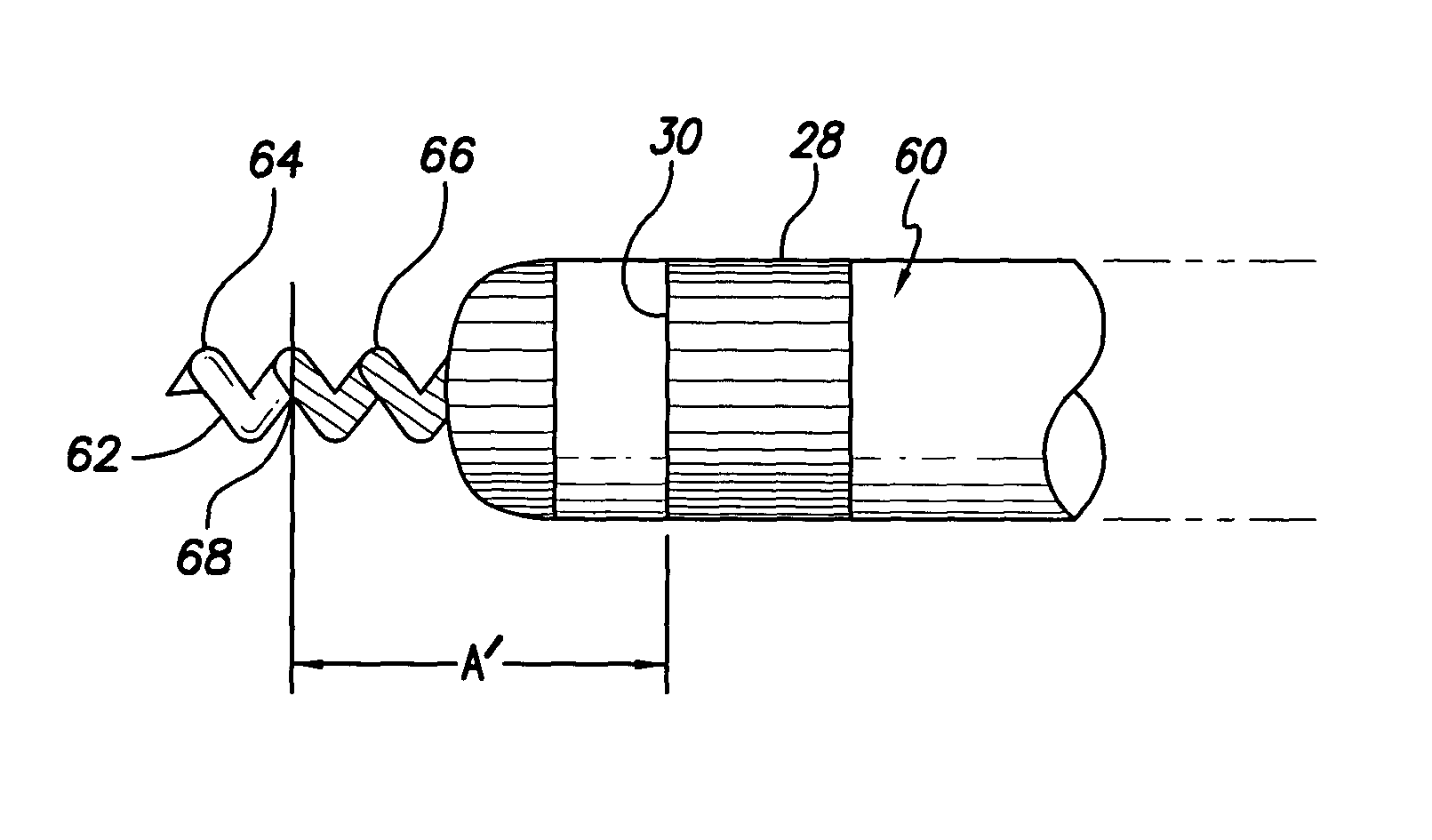
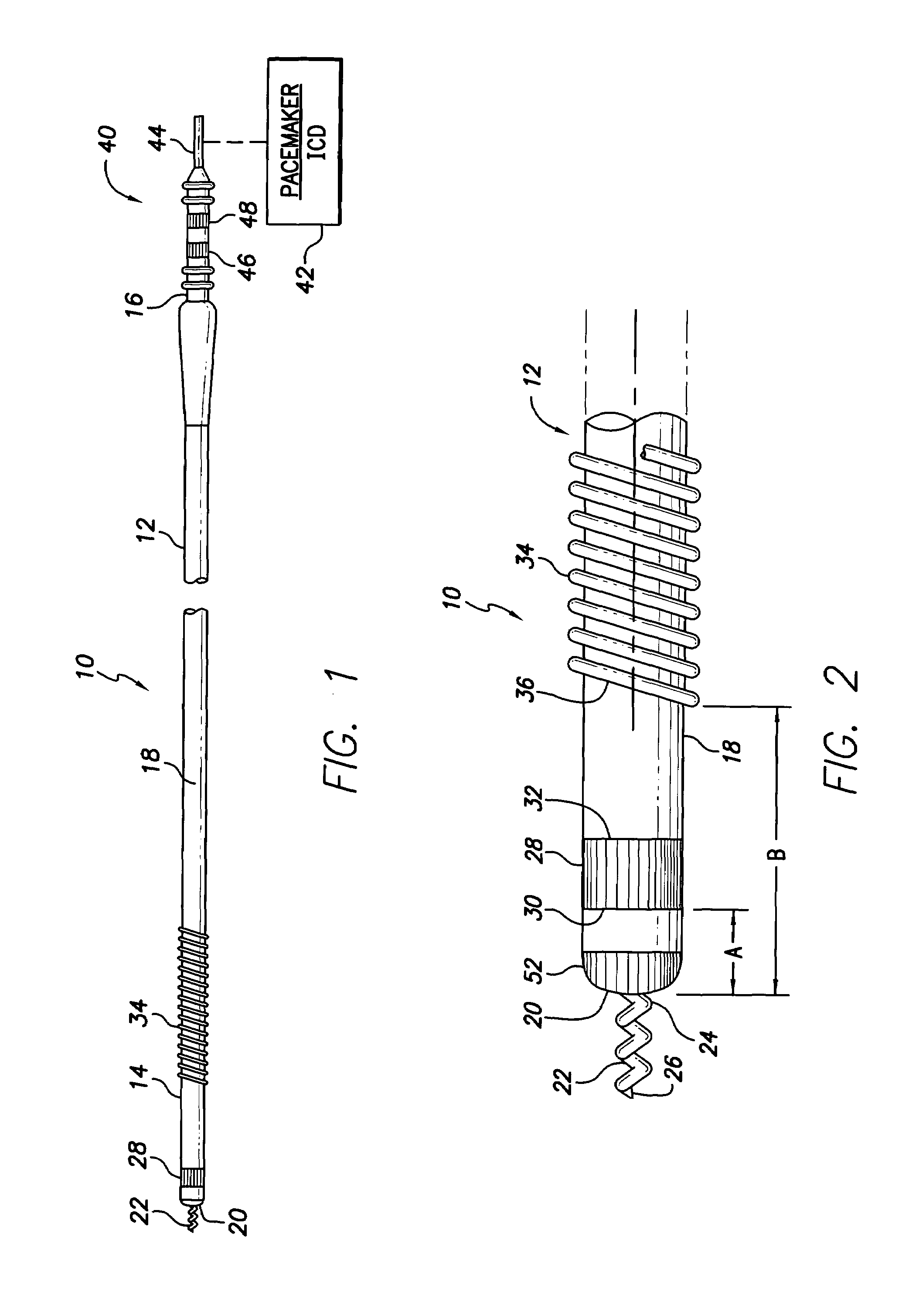
[0027]With reference to FIGS. 1 and 2, there is shown a bipolar pacing and sensing lead 10 in accordance with a preferred embodiment of the present invention for epicardial or endocardial placement in electrical contact with the heart. The lead 10 includes a lead body 12 comprising a distal end 14 and a proximal end 16 joined by a tubular sheath or housing 18 made of an insulating, biocompatible, biostable material such as silicone rubber or polyurethane.

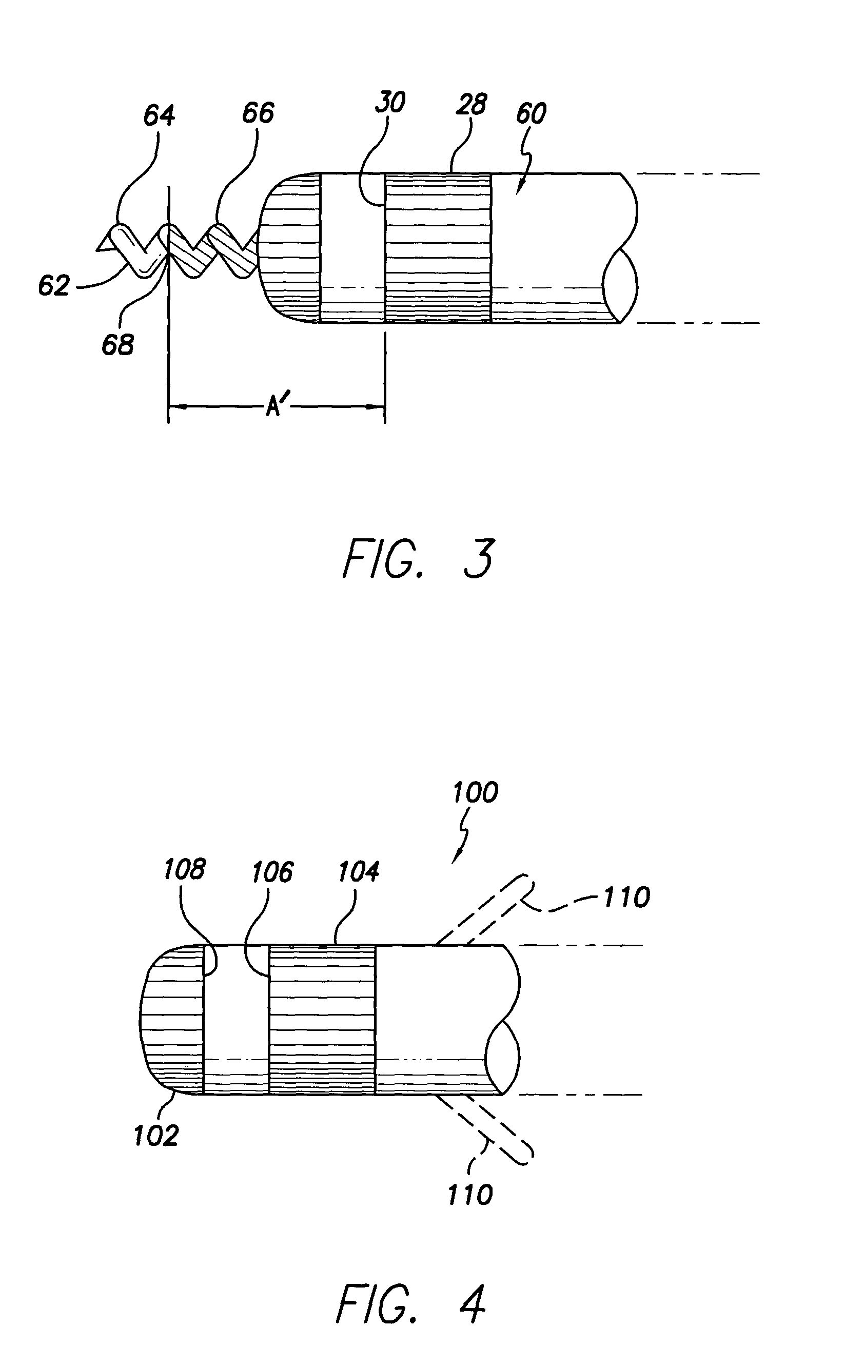
[0028]The distal end 14 of the lead body 12 terminates at a distal extremity 20. The distal extremity 20 defines a central aperture through which a rotatable, helical screw-in tip electrode 22 may ...


PUM


Abstract

A bipolar pacing and sensing lead incorporates a range of active surface areas for each of the anode and cathode electrodes, and a range of inter-electrode spacings between the anode and cathode electrodes which, in combination, provide acceptable near-field signal amplitudes and attenuate the amplitudes of unwanted signals, such as far-field R-waves, far-field P-waves, and T-waves.

Description

CROSS-REFERENCE TO RELATED APPLICATIONS[0001]This application claims the benefit of U.S. Provisional Application No. 60 / 476,472, filed Jun. 5, 2003.FIELD OF THE INVENTION[0002]The present invention relates generally to implantable medical electrical leads and more particularly to bipolar pacing and sensing leads having electrodes arranged to suppress or attenuate undesirable signals, such as far-field signals and T-waves.BACKGROUND OF THE INVENTION[0003]Cardiac pacemaker lead systems fulfill two functions. The first function is to provide an electrical conduit by which a pacemaker output pulse is delivered to stimulate the local tissue adjacent to the distal tip of the lead. The second function is to sense local, intrinsic cardiac electrical activity that takes place adjacent to the distal tip of the lead.[0004]One of the problems with such pacing and sensing lead systems is their inability to suppress or attenuate the voltage levels of far-field electrical signals. These signals ar...

Claims


Application Information

Patent Timeline
03 Jun 2008
Publication
US7383091B1
IPC
A61N1/05
CPC
A61N1/056; A61N1/0573
Inventors
CHITRE, YOUGANDH; MIN, XIAOYI