Hybrid engine

a hybrid engine and turbocharger technology, applied in hybrid vehicles, machines/engines, vehicle sub-unit features, etc., can solve the problems of reducing the amount of energy remaining in the exhaust gas after passing through the turbocharger and limited the amount of power that can be extracted with a second turbine. achieve the effect of increasing system output and efficiency

Active Publication Date: 2008-06-10
DEERE & CO
View PDF12 Cites 28 Cited by
  • Summary
  • Abstract
  • Description
  • Claims
  • Application Information

AI Technical Summary

Benefits of technology

[0006]The present invention provides a way to significantly increase the output capability of an internal combustion engine. The first stage of power increases come from application of turbo compounding technologies that exploit waste exhaust heat not recovered from the turbocharger. This technology requires a second stage turbine coupled to a high speed generator. The electrical output of the generator is then coupled back to the engine using an electrical motor. Such a device can increase specific engine output from 10 to 30% with good efficiency.
[0007]The present invention exploits the turbo compounding hardware for additional power growth. By adding a combustor independent of the engine, additional hot gasses can be provided that can be used to increase the output of the turbo compounding turbine. Substantial additional power output is possible with such an arrangement. The incremental efficiency may not be as high as the base engine, but the invention is useful where peak power is required only occasionally. This would allow a small engine to run at a higher duty cycle, improving system efficiency in the high usage area of the operating envelope.
[0009]The invention comprises, in another form thereof, an internal combustion engine, a second stage electric turbo compounding device, and a motor / generator that recycles turbo compounding output back to the engine in mechanical form. This machine can be coupled to a micro turbine which includes a compressor and turbine mounted onto the rotor of a high speed motor / generator. A combustor is connected between the compressor and turbine. Combustor gasses blow through the turbine generating electrical power completely independent of the reciprocating engine. Electrical output is easily coupled to the reciprocating engine turbo compounding device using a DC link. The combined output uses the existing motor / generator to convert all the electrical power back to rotating shaft power for mechanically driving loads. Gaseous output from the micro turbine can be further expended through the turbo compounding turbine using a split entry volute for added system output and efficiency.

Problems solved by technology

The amount of energy remaining in the exhaust gas after passing through the turbocharger is somewhat diminished, therefore the amount of power that can be extracted with a second turbine is limited.

Method used


Image

  • Hybrid engine
  • Hybrid engine
  • Hybrid engine

Examples


Embodiment Construction

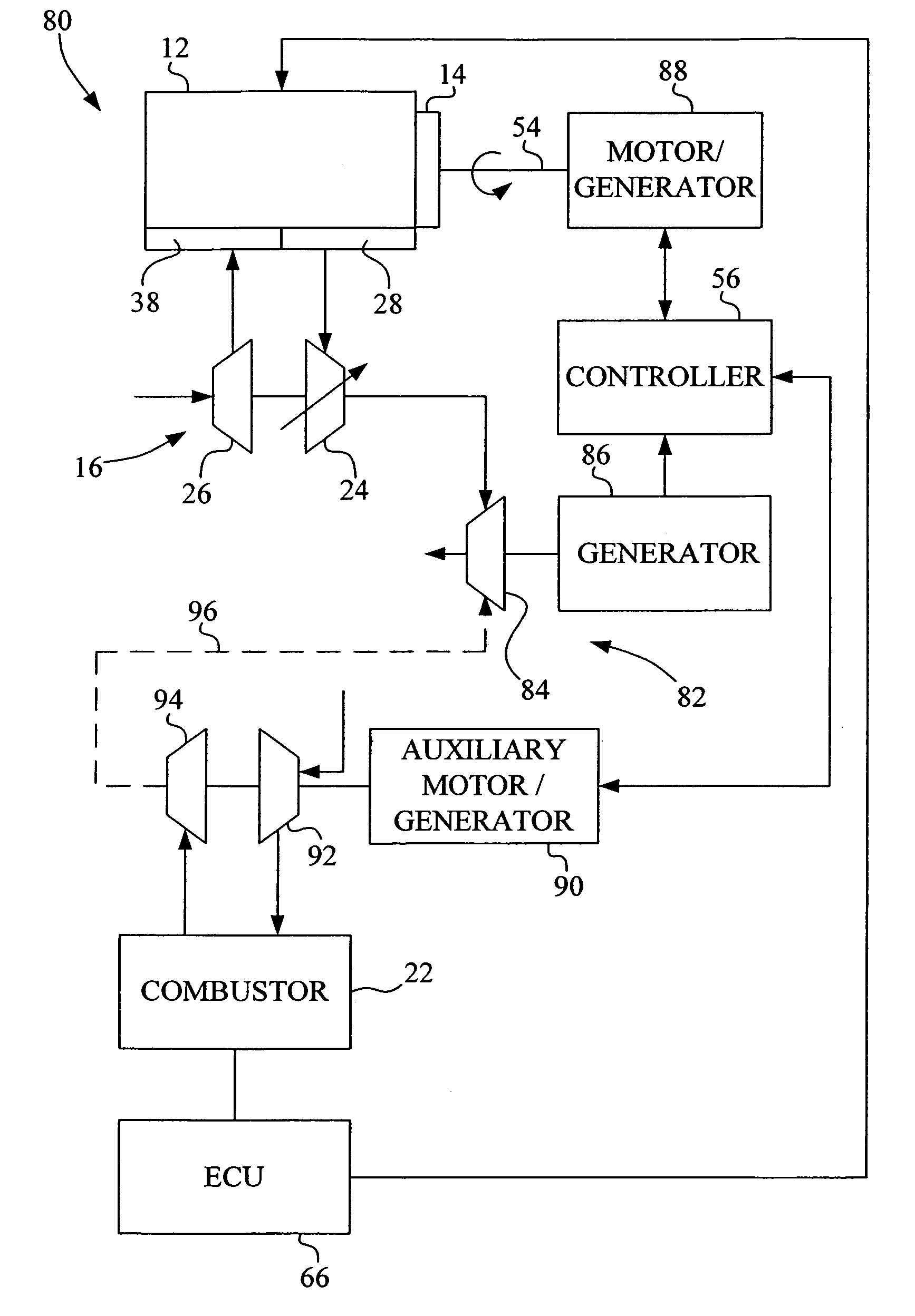
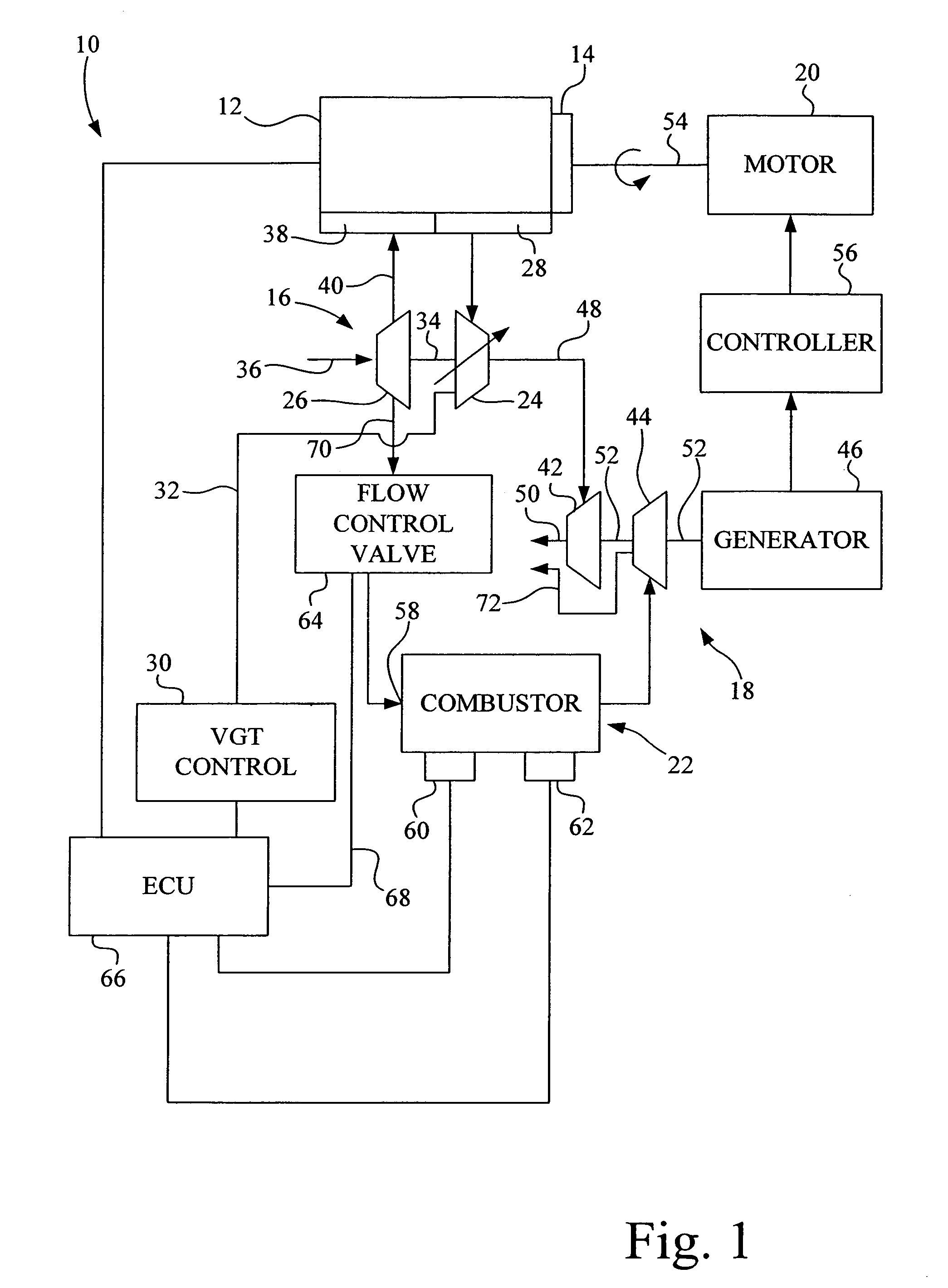
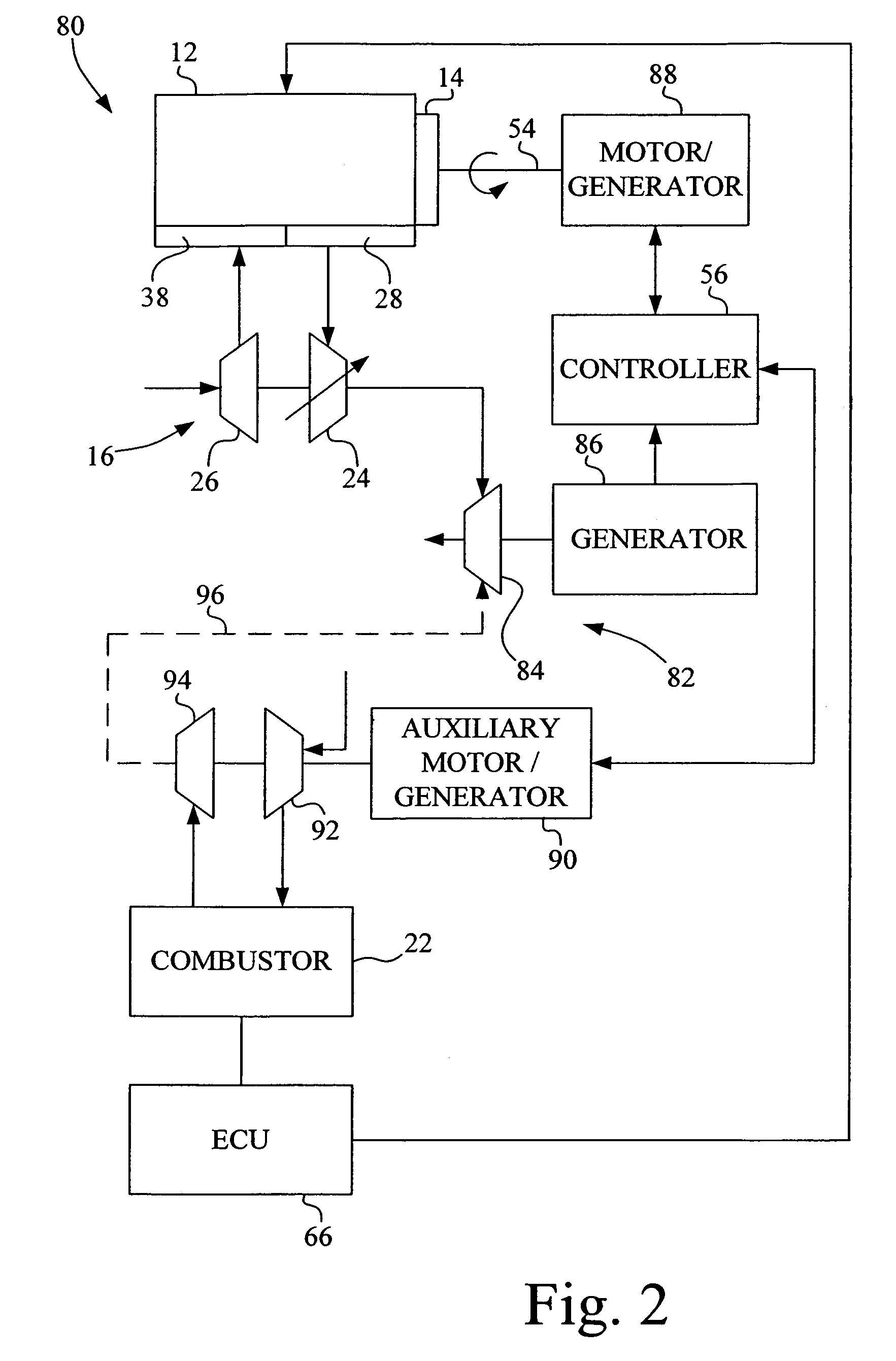
[0012]Referring now to the drawings, and more particularly to FIG. 1, there is shown an embodiment of an IC engine 10 of the present invention. In general, IC engine 10 includes a block 12 carrying a flywheel 14, turbocharger 16, turbogenerator 18, motor 20 and combustor 22.

[0013]Cylinder block 12 defines a multi-cylinder internal combustion engine, with each cylinder carrying a respective piston which is coupled with a crankshaft (not shown) attached to flywheel 14. In the embodiment shown, cylinder block 12 forms part of a multi-cylinder diesel engine which may include any desired number of cylinders, typically an even number between two and twelve cylinders.

[0014]Turbocharger 16 includes a turbine 24 and a compressor 26. Turbine 24 is rotatably driven by exhaust gases discharged from exhaust manifold 28. In the embodiment shown, turbine 24 is configured as a variable geometry turbine (VGT), as indicated by the diagonal arrow through turbine 24, but may also be configured as a fix...


PUM


Abstract

An internal combustion engine includes an exhaust manifold; an intake manifold; and a turbocharger including a turbine in communication with the exhaust manifold, and a compressor in communication with the intake manifold. An electrical generator is coupled with the turbine. A motor receives electrical input power from the generator and provides mechanical output power. A combustor selectively provides additional input power to the motor.

Description

FIELD OF THE INVENTION[0001]The present invention relates to internal combustion engines, and, more particularly, to engines with electric turbo compounding.BACKGROUND OF THE INVENTION[0002]Internal combustion (IC) engines may be of a multi-cylinder or gas turbine design. It is common for a multi-cylinder engine to include a turbocharger having a turbine which is rotatably driven by exhaust gases and a compressor providing compressed charge air to the combustion cylinders. The turbocharger uses otherwise spent exhaust gases to increase the power output from the engine.[0003]It is known to use the exhaust gases which are discharged from the turbine of the turbocharger to rotatably drive a second turbine connected to an electrical generator. The electrical generator is selectively coupled through a controller to a motor providing additional mechanical input power to the flywheel of the multi-cylinder engine. The amount of energy remaining in the exhaust gas after passing through the t...

Claims


Application Information

Patent Timeline
Patent Type & Authority Patents(United States)
IPC IPC(8): F02B33/44
CPCB60K6/24B60K6/485F01N5/04F02B37/164F02B37/166F02D23/02F02D29/06F02B3/06F02B37/24F02B2700/026Y02T10/6226Y02T10/6295Y02T10/144Y02T10/16B60Y2400/435F02B41/10F02B63/042F02C6/12F05D2220/76Y02T10/12Y02T10/62
Inventor VUK, CARL THOMAS
Owner DEERE & CO
Why Eureka
Try Eureka