Fuel cell system

a fuel cell and system technology, applied in the field of fuel cell systems, can solve the problems of increasing the total size increasing the complexity and size of the piping system, and affecting so as to achieve the effect of improving the freedom of installation of the fuel cell stack

Active Publication Date: 2008-06-10
HONDA MOTOR CO LTD
View PDF10 Cites 7 Cited by
  • Summary
  • Abstract
  • Description
  • Claims
  • Application Information

AI Technical Summary

Benefits of technology

[0010]The invention solves this type of problem and has its object to provide a fuel cell system, in which the first and the second fuel cell stacks structure are connected in parallel to each other with a simple and a compact structure, and also it secures a desired electric power generating performance.
[0011]Also, it is an object of the invention to provide a fuel cell system that is simple and compact in structure, can be easily assembled in various locations of installation, and is excellent in handling quality.
[0014]In this manner, it suffices that the first and second fuel cell stacks have the same structure and be arranged with polarities thereof reversed. Accordingly, the first and second fuel cell stacks are sharply reduced in manufacturing cost as compared with the case where the first and second fuel cell stacks are different in structure from each other.
[0016]Thereby, it becomes possible to distribute the fuel gas, the oxidizer gas, the coolant evenly to the first and second fuel cell stacks from the manifold piping, so that the first and second fuel cell stacks can surely exhibit a desired electric power generating performance. Further, the manifold piping is simplified in piping structure and space-saving is easily achieved.
[0017]Also, with the fuel cell system according to the invention of claim 2, the first and second fuel cell stacks comprise series connections connected electrically to a side of the one ends, to which the manifold piping is mounted. Thereby, a electric potential difference between the one sides of the first and second fuel cell stacks is decreased, so that no shunt current through liquid is caused in the manifold piping mounted on the one sides. Accordingly, for example, electrolytic corrosion of metallic parts is effectively prevented.
[0020]Thereby, a piping structure, in which the manifold piping is connected to the first to sixth through-holes of the first end plate and the seventh to twelfth through-holes of the second end plate are closed, and a piping structure, in which the manifold piping is connected to the seventh to twelfth through-holes of the second end plate and the first to sixth through-holes of the first end plate are closed, are selectively adopted. Accordingly, an optimum piping connection is enabled according to a location, in which the fuel cell stack is installed, and so the fuel cell stack is effectively improved in freedom of installation.

Problems solved by technology

In this occasion, it causes a problem such that unit cells are considerably extended in a stacking direction, whereby a fuel gas ends up being supplied insufficiently to the respective unit cells.
Therefore, the piping system becomes complicated and large in size, and the whole size of the fuel cell stacks becomes also considerably large one.
Thereby, space factor is decreased which pointed out a problem of the fuel cell disclosed in the Patent Document being not useful or efficient for the vehicle-mounting application.

Method used


Image

  • Fuel cell system
  • Fuel cell system
  • Fuel cell system

Examples


first embodiment

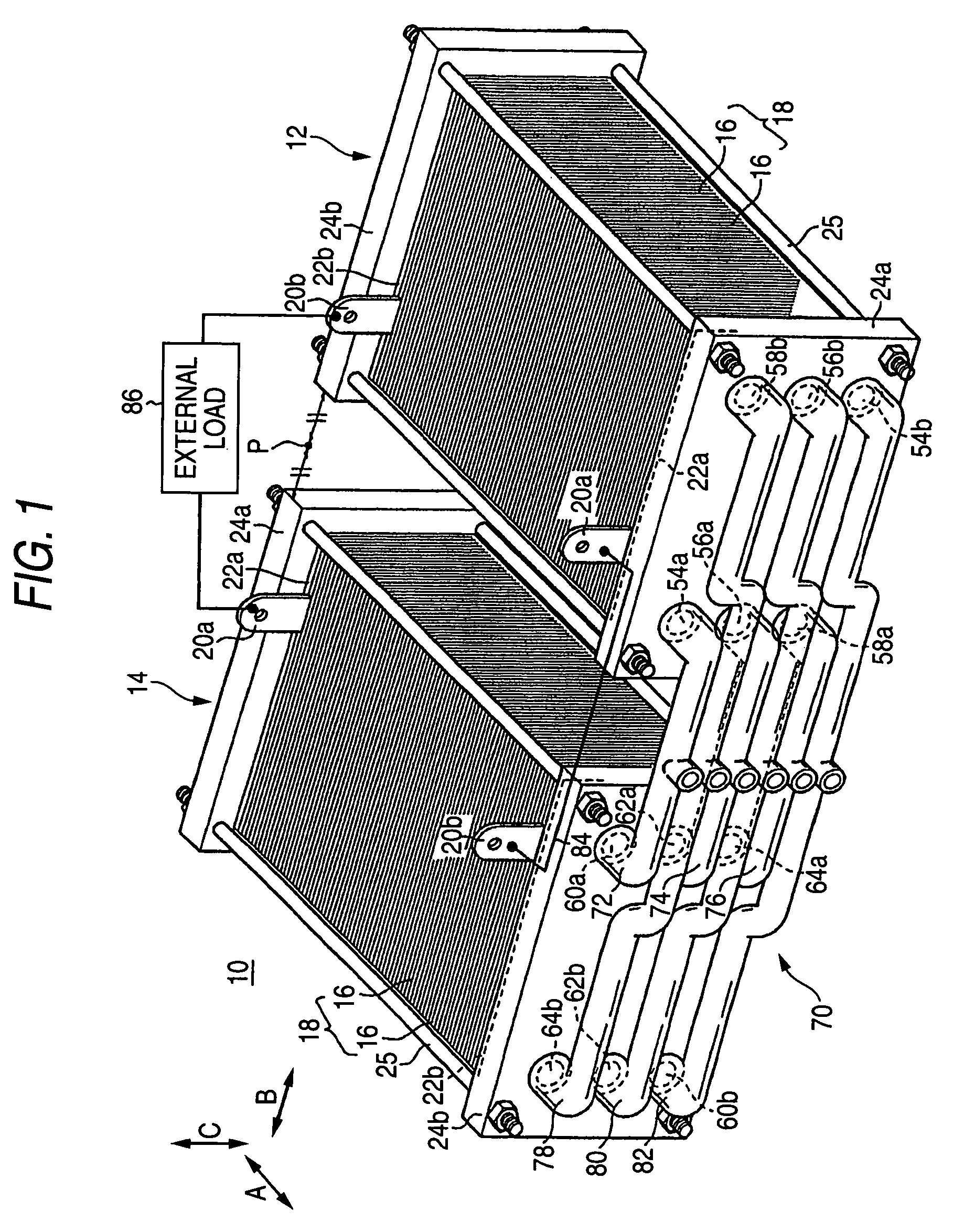
[0028]FIG. 1 is a perspective view schematically showing an entire fuel cell system 10 according to the invention.

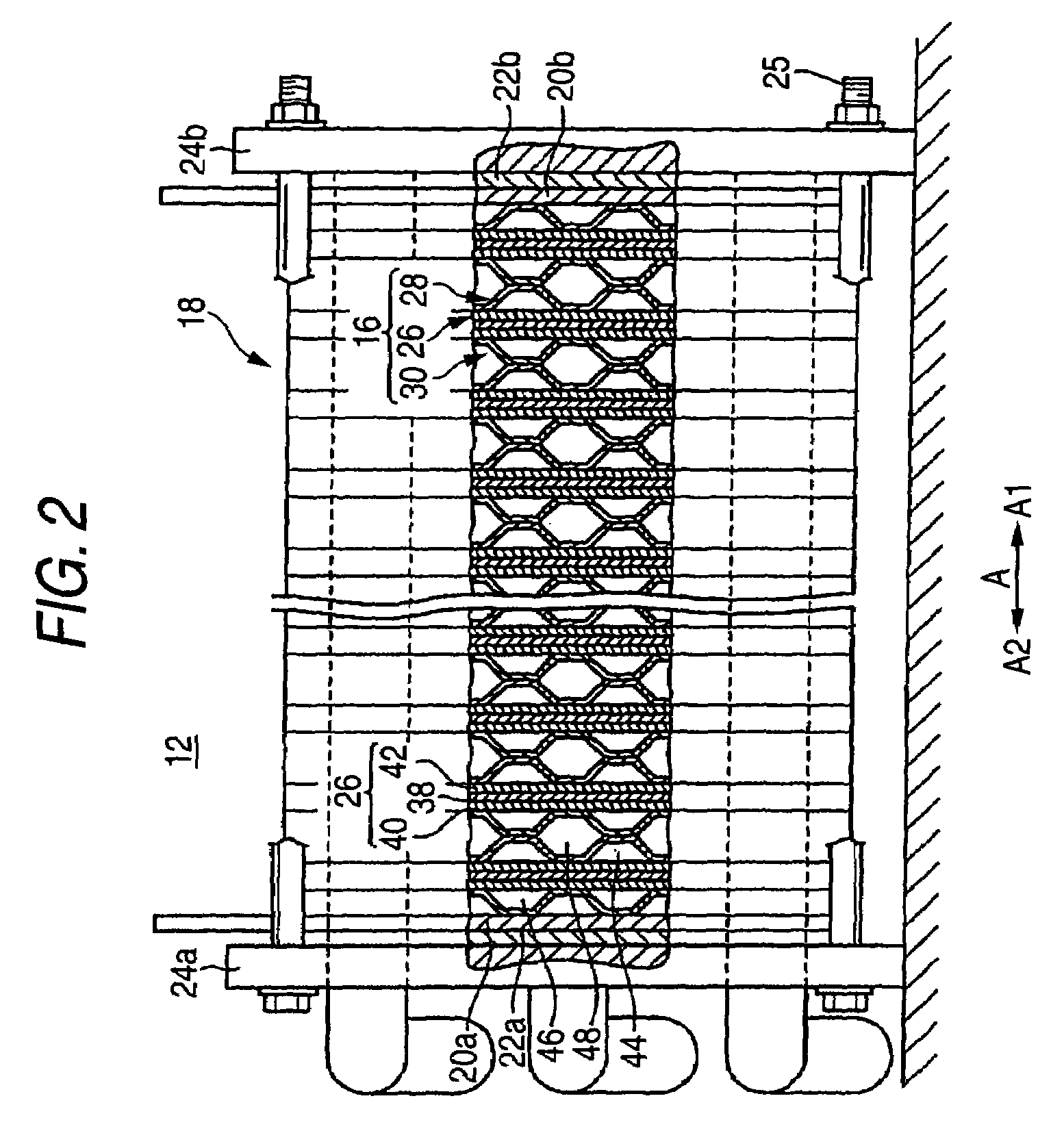
[0029]The fuel cell system 10 comprises a first fuel cell stack 12 and a second fuel cell stack 14, which are arranged in parallel to each other along a horizontal direction (direction indicated by an arrow A) and with polarities thereof reversed. As shown in FIGS. 1 and 2, the first fuel cell stack 12 comprises a stacked body 18, in which a plurality of unit cells 16 are stacked in the direction indicated by the arrow A, and first and second terminal plates 20a, 20b, first and second insulator plates 22a, 22b, and first and second end plates 24a, 24b, respectively, are arranged outward in this order on both ends of the stacked body 18 in a stacking direction. The first and second end plates 24a, 24b are clamped via a plurality of clamp rods 25 in the stacking direction such that a desired clamp load is applied to the stacked body 18.

[0030]As shown in FIGS. 2 and 3, the ...

second embodiment

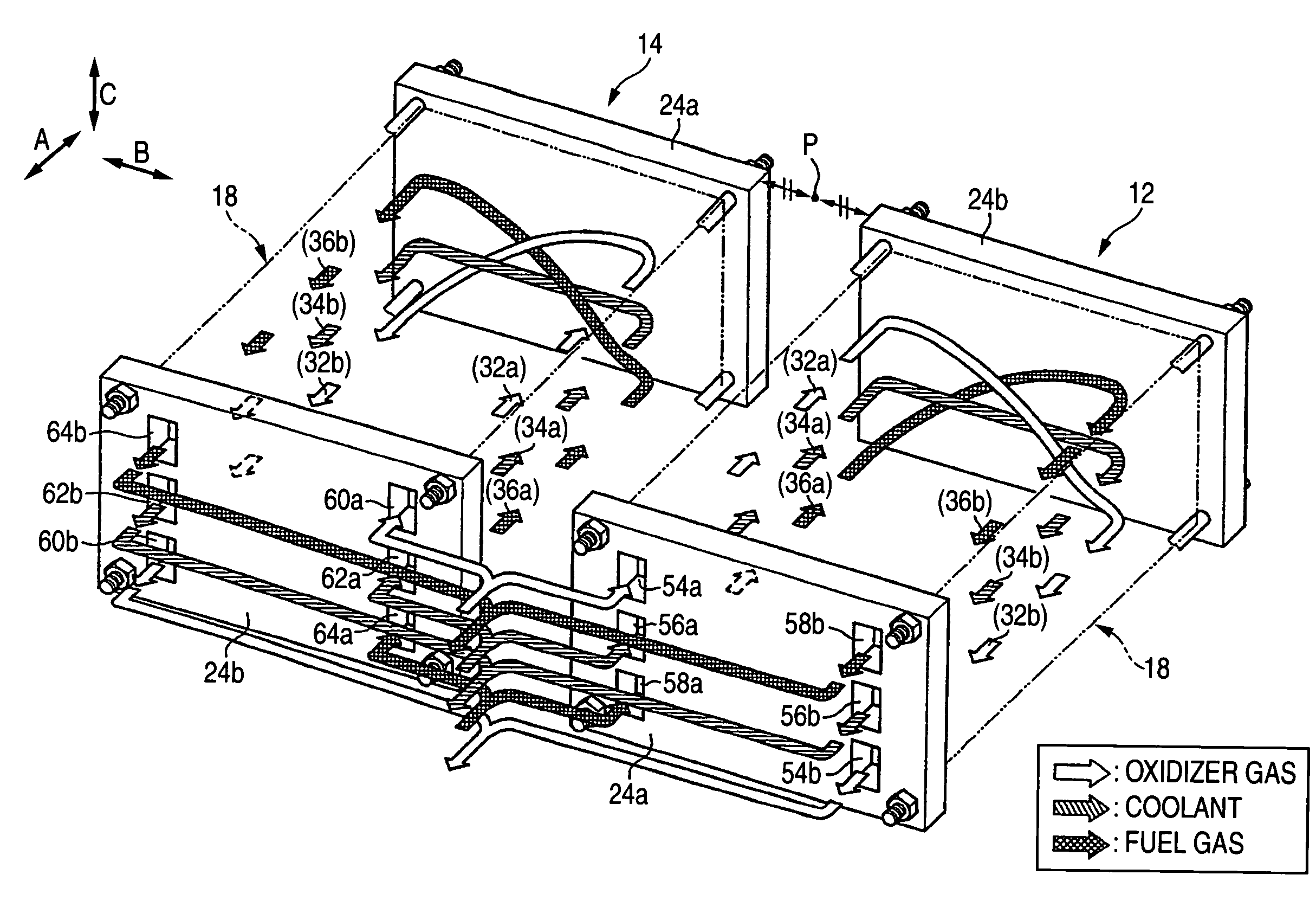
[0061] the fuel cell system 90 comprises a single fuel cell stack 92. A first end plate 24a that constitutes the fuel cell stack 92 is provided with an oxidizer-gas inlet 54a, a coolant inlet 56a, a fuel-gas inlet 58b, a fuel-gas outlet 58b, a coolant outlet 56b, and an oxidizer-gas outlet 54b. A second end plate 24b that constitutes the fuel cell stack 92 is provided with an oxidizer-gas inlet 60a, a coolant inlet 62a, a fuel-gas inlet 64b, an fuel-gas outlet 64b, a coolant outlet 62b, and an oxidizer-gas outlet 60b.

[0062]In the second embodiment structured in this manner, the first end plates 24a, 24b are formed with through-holes (not shown). Accordingly, a piping structure, in which a manifold piping 70 is connected to the first end plate 24a and the second end plate 24b is closed, and a piping structure, in which a manifold piping 70 is connected to the second end plate 24b and the first end plate 24a is closed, are selectively adopted.

[0063]Thereby, there is produced an effec...


PUM

PropertyMeasurementUnit
polaritiesaaaaaaaaaa
DC electric energyaaaaaaaaaa
energyaaaaaaaaaa

Abstract

First and second fuel cell stacks having a simple and compact structure are connected in parallel to each other to enable ensuring a desired electric power generating performance. The first and second fuel cell stacks have the same structure and are arranged in parallel to each other with polarities thereof reversed. A manifold piping is mounted to one ends of the first and second fuel cell stacks. In order to supply an oxidizer gas, a fuel gas, and a coolant to the first and second fuel cell stacks, at least an oxidizer-gas supply pipe, a fuel-gas supply pipe, and a coolant supply pipe in the manifold piping are provided to be symmetrical with respect to the first and second fuel cell stacks.

Description

BACKGROUND OF THE INVENTION[0001]1. Field of the Invention[0002]The present invention relates to fuel cell system provided with fuel cell stacks, in which a plurality of unit cells comprising a membrane electrode assembly having a pair of electrodes on both sides of an electrolyte are stacked horizontally so as to be interposed by separators.[0003]2. Description of the Related Art[0004]For example, a solid polymer electrolyte fuel cell comprises a unit cell or cells, each having a membrane electrode assembly being interposed by the separators. Further, said membrane electrode assembly is comprised of an anode-side electrode and a cathode-side electrode to be provided on both sides of an electrolyte (electrolyte membrane) so as to be opposed each other, where said electrolyte is composed of a polymer ion-exchange membrane (positive ion-exchange membrane). This type of unit cell comprises membrane electrode assemblies and separators in general, a predetermined numbers of said assembli...

Claims


Application Information

Patent Timeline
Patent Type & Authority Patents(United States)
IPC IPC(8): H01M2/14H01M2/08H01M8/00H01M8/02H01M8/04H01M8/10H01M8/24
CPCH01M8/02H01M8/0258H01M8/241H01M8/2465H01M8/249H01M8/04007H01M8/04089Y02E60/50H01M8/2483H01M8/0267H01M8/2484H01M8/2418
Inventor SATO, MASAHIKOKIKUCHI, HIDEAKIFUJII, YOSUKE
Owner HONDA MOTOR CO LTD
Why Eureka
Try Eureka