
Wideband radial power combiner/divider fed by a mode transducer

a radial power combiner and mode transducer technology, applied in the direction of electrical equipment, multiple-port networks, coupling devices, etc., can solve the problems of reducing the efficiency of individual mmics, reducing the efficiency of individual tube devices, and losing half of rf power output, etc., to achieve the effect of facilitating replacement of tube-based flight, unparallel size, weight and power combination

Inactive Publication Date: 2008-06-10
NAT AERONAUTICS & SPACE ADMINISTATION U S GOVERNMENT AS REPRESENTED BY THE ADMINISTATOR OF THE
View PDF8 Cites 56 Cited by
  • Summary
  • Abstract
  • Description
  • Claims
  • Application Information

AI Technical Summary

Benefits of technology

[0016]It is a more specific object to provide a low-loss, compact radial power divider / combiner for use in wideband high-frequency (15% bandwidth in the 30-36 GHz range) Solid State Power Amplifier (SSPA) applications that offers an unparalleled size, weight, and power combination.
[0017]It is another object to provide a radial power divider / combiner that facilitates replacement of tube-based flight and ground amplifiers with solid state MMIC-based amplifiers for use in earth-orbiting defense missions and radar applications, as well as satellite secure communications systems requiring large bandwidths (secure satellite uplinks, downlinks, and cross-links), etc.
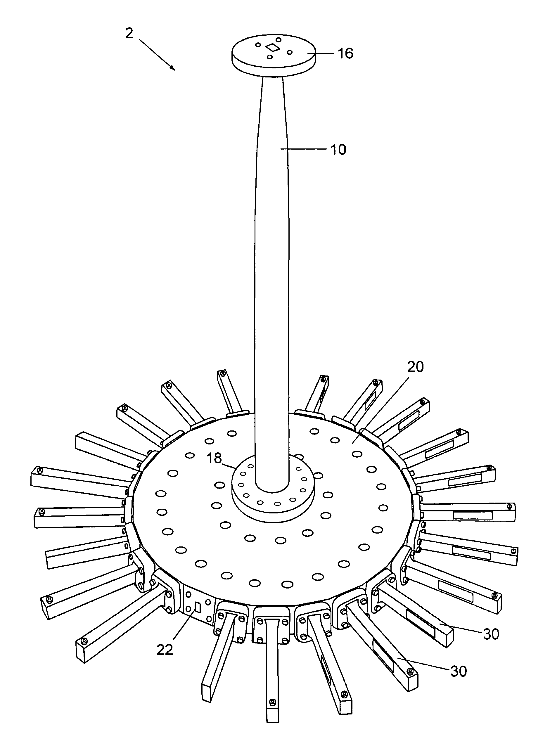
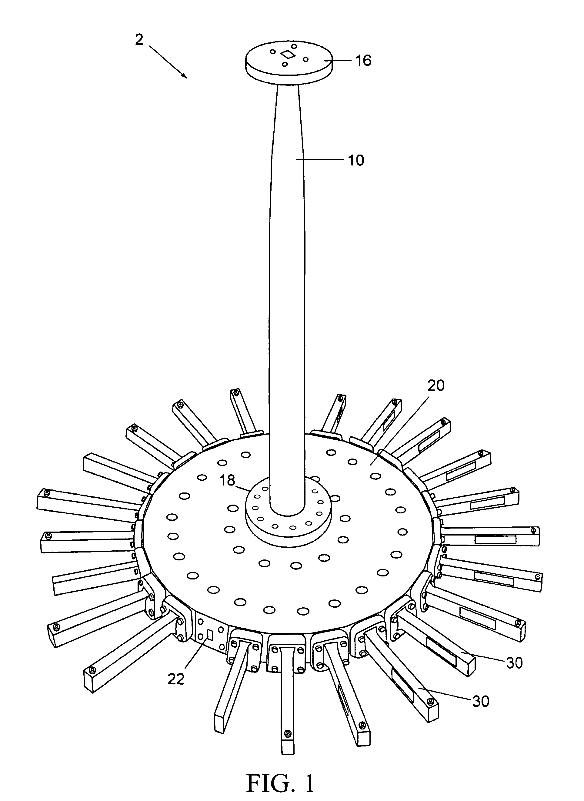
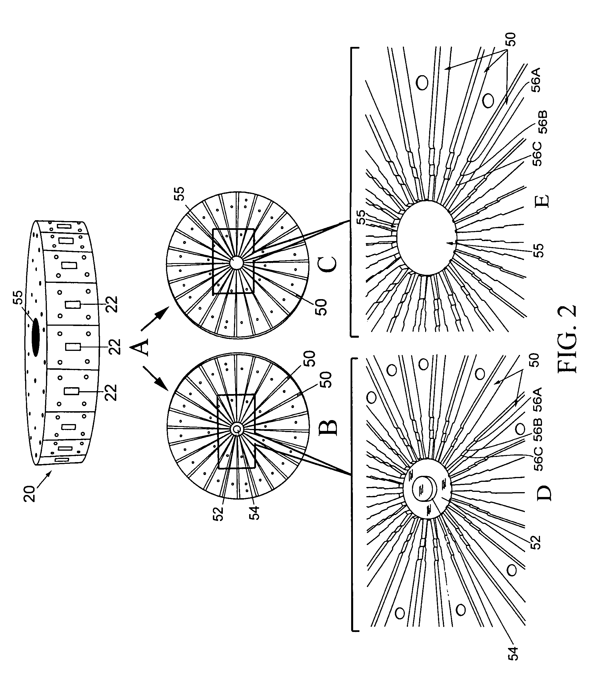
[0018]According to the present invention, the above-described and other objects are accomplished by providing a novel radial power combiner / divider with a higher order of power combining / dividing within a wide high-frequency bandwidth. The radial power combiner / divider generally comprises an axially-oriented mode transducer coupled to a radial base. The unique mode transducer transduces circular TE01 waveguide into rectangular TE10 waveguide, and the unique radial base combines / divides a plurality of ports into / from the single circular TE01 waveguide end of the transducer. The radial base incorporates full-height waveguides at the plurality of ports that are stepped down to reduced-height waveguides using stepped impedance transformers. This presents a stepped-impedance configuration that allows for reduced height waveguides inside the radial base (the height of the waveguides otherwise limiting the order N of combining), and hence a higher order combiner / divider. The reduced-height waveguides in the base converge radially to a matching post at the bottom center of the radial base which matches the reduced height rectangular waveguides into the circular waveguide that feeds the mode transducer. The matching post allows for a better output match at the circular waveguide of the radial base, which in turn with the mode transducer allows for a good output match of the divider / combiner as a whole.

Problems solved by technology

A fundamental problem with conventional SSPA technology is that individual MMICs produce less power and operate at lower efficiency compared to the individual tube devices.
Existing power-combiners such as the in-phase Wilkinson combiner or the 90-degree branch-line hybrid combine a number of binary combiners in a cascaded manner, but this architecture becomes very lossy and cumbersome when the number of combined amplifiers becomes large.
A 3 dB insertion loss infers that half of the RF power output is lost, and this is unacceptable for most applications.
The stripline radial combiner, using multi-section impedance transformers and isolation resistors, still suffers excessive loss at Ka-band, mainly because of the extremely thin substrate (<10 mil) required at Ka-band.
The coaxial waveguide approach uses oversized coaxial cable, which introduces moding problems and, consequently, is useful only at low frequencies.
The quasi-optical combiner uses hard waveguide feed horns at both the input and output to split and combine the power, and these are very large and cumbersome.

Method used


Image

  • Wideband radial power combiner/divider fed by a mode transducer
  • Wideband radial power combiner/divider fed by a mode transducer
  • Wideband radial power combiner/divider fed by a mode transducer

Examples


Embodiment Construction

[0033]The present invention is a radial power divider and / or combiner for dividing / combining a increased number N of amplifier signals within a wide bandwidth using compact radial format. The radial power combiner / divider generally comprises an axially-oriented mode transducer coupled to a radial base. The mode transducer transduces circular TE01 waveguide into rectangular TE10 waveguide, and the radial base combines / divides a plurality of ports into / from the single circular TE01 waveguide end of the transducer. The radial base is formed with a plurality of internal waveguides leading from peripheral output ports and converging radially to the center, the internal waveguides incorporating a stepped impedance configuration that allows a reduction in their size and increase in the order N of combining. The base also includes a matching post at the bottom center which matches the reduced height rectangular waveguides into the circular waveguide that feeds the mode transducer.

[0034]The ...


PUM


Abstract

A radial power combiner / divider capable of a higher order (for example, N=24) of power combining / dividing and a 15% bandwidth (31 to 36 GHz). The radial power combiner / divider generally comprises an axially-oriented mode transducer coupled to a radial base. The mode transducer transduces circular TE01 waveguide into rectangular TE10 waveguide, and the unique radial base combines / divides a plurality of peripheral rectangular waveguide ports into a single circular TE01 waveguide end of the transducer. The radial base incorporates full-height waveguides that are stepped down to reduced-height waveguides to form a stepped-impedance configuration, thereby reducing the height of the waveguides inside the base and increasing the order N of combining / dividing. The reduced-height waveguides in the base converge radially to a matching post at the bottom center of the radial base which matches the reduced height rectangular waveguides into the circular waveguide that feeds the mode transducer.

Description

CROSS-REFERENCE TO RELATED APPLICATIONS[0001]The present application derives priority from U.S. Provisional Application No. 60 / 663,330 filed 18 Mar. 2005.STATEMENT OF GOVERNMENT INTEREST[0002]The invention described hereunder was made in the performance of work under a NASA contract, and is subject to the provisions of Public Law #96-517 (35 U.S.C. 202) in which the Contractor has elected not to retain title.BACKGROUND[0003]a. Field of invention[0004]The invention relates to radial power divider / combiners and, in particular, to radial power divider / combiners that are suitable for use in solid-state power-amplifier (SSPA) devices.[0005]b. Background of the invention[0006]Solid State Power Amplifiers (SSPAs) are used in a variety of applications ranging from satellites, radar, and other RF applications requiring high output power. Typical SSPAs can achieve signal output levels of more than 10 watts using solid-state amplifiers such as Monolithic Microwave Integrated Circuits (MMICs), ...

Claims


Application Information

Patent Timeline
IPC IPC(8): H01P5/12H03H7/38
CPCH01P5/12
Inventor EPP, LARRY W.HOPPE, DANIEL J.KELLEY, DANIELKHAN, ABDUR R.
Owner NAT AERONAUTICS & SPACE ADMINISTATION U S GOVERNMENT AS REPRESENTED BY THE ADMINISTATOR OF THE
Learn More