Cotton harvester row unit speed synchronization control

a technology of row unit speed and control, applied in the field of cotton harvesters, can solve the problems of loss of synchronization, ground speed and unit speed synchronization over time, adversely affecting field efficiency and harvested cotton quality, etc., and achieve the effect of improving the drive structure of the cotton harvester

Active Publication Date: 2008-06-10
DEERE & CO
View PDF16 Cites 11 Cited by
  • Summary
  • Abstract
  • Description
  • Claims
  • Application Information

AI Technical Summary

Benefits of technology

[0006]It is therefore an object of the present invention to provide an improved cotton harvester drive structure. It is another object to provide such a structure which overcomes most or all of the aforementioned problems.
[0007]It is a further object of the invention to provide an improved cotton harvester row unit drive structure which facilitates ground speed versus unit speed adjustment with true picking unit synchronization at all ground speeds regardless of transmission gear ratio or selected speed ranges. It is another object to provide such a structure having a sync ratio adjustment. It is yet another object to provide a cotton harvester row unit drive structure that includes a non-linear ground speed versus row unit speed capability.
[0010]A detector senses cotton remaining on the plants after they pass through the picking units and provides feedback to the electronic controller. The crop remaining feedback is used to automatically make adjustments to the speed ratio to reduce the amount of cotton left in the field. The detector can be a camera focused on the plants exiting the row unit housing or on the rows of harvested crop behind the harvester. Open cotton bolls remaining on the plants present a high white content to the camera detector to provide an easily processed signal for determining the approximate amount of cotton remaining on the plants. The speed of the picking units can be increased relative to ground speed by decreasing harvester speed or increasing unit speed when the signal from the detector indicates that unharvested cotton is above a preselected maximum level. When the signal indicates that unharvested cotton falls below a minimum acceptable level, the controller can automatically increase ground speed relative to unit speed to increase harvest productivity. The sync ratio input can be adjusted in the automatic control mode to modify the automatic control for the desired balance between acceptable amounts of crop left in the field and / or cotton quality and machine productivity. The automatic control helps maximize productivity and reduce crop damage, particularly in fields with highly varying-field and crop conditions, without operator fatigue.
[0011]The drive structure facilitates non-linear ground speed versus unit speed adjustment with true picking unit synchronization at all ground speeds regardless of transmission gear ratio or selected speed ranges. The row unit speed can be increased relative to the ground speed, for example, when the row units are first entering the rows to be harvested and the harvester is moving more slowly.
[0012]The synchronization is unaffected by drive train efficiency changes and wear. The operator can adjust picking aggressiveness on-the-go to slow or speed row unit drive relative to harvester speed to best match picking conditions and achieve the desired balance between crop loss and harvester speed for optimum productivity. In addition, the drive system allows the hydro control handle to be placed in the neutral position during tether operations. By providing electronic synchronization and eliminating a manual synchronization process during manufacturing or servicing of the harvester, including component replacement, substantial time savings is achieved. The drive structure provides improved efficiency and cotton quality by allowing ground speed to unit speed synchronization at all speeds and with adjustment capability to meet changing crop and field conditions. With electronic control, if the transmission is in gear and the units are engaged, the units will only operate when the machine is intended to move in the forward direction. The electronic control normally prevents unit operation when the harvester is reversed. If desired, the operator can move the units in reverse by putting the machine in neutral with the park brake on and then moving the hydro handle to the reverse position.

Problems solved by technology

Synchronization is lost when the transmission shifts gear or the harvester is turned from the forward direction.
In addition, ground speed and unit speed synchronization is lost over time because of efficiency changes; tolerance stack-up, and part wear including tire tread wear.
Improper synchronization adversely affects field efficiency and harvested cotton quality.
The mechanical drive systems do not allow easy adjustment of speed ratios to accommodate for variable field and plant conditions.
In low yield cotton, the operator often increases harvester speed, but a proportional increase in drum speed may not be warranted since there is less cotton to engage in the row.
Over-speed of the picking units increases component wear.
Such operation in reverse can cause the slip clutch to activate and can drag cotton backwards against the moistener columns and doffers to adversely affect picking unit adjustment.
Present mechanical drive systems require complex linkages and a relatively large number of moving parts.

Method used


Image

  • Cotton harvester row unit speed synchronization control
  • Cotton harvester row unit speed synchronization control
  • Cotton harvester row unit speed synchronization control

Examples


Embodiment Construction

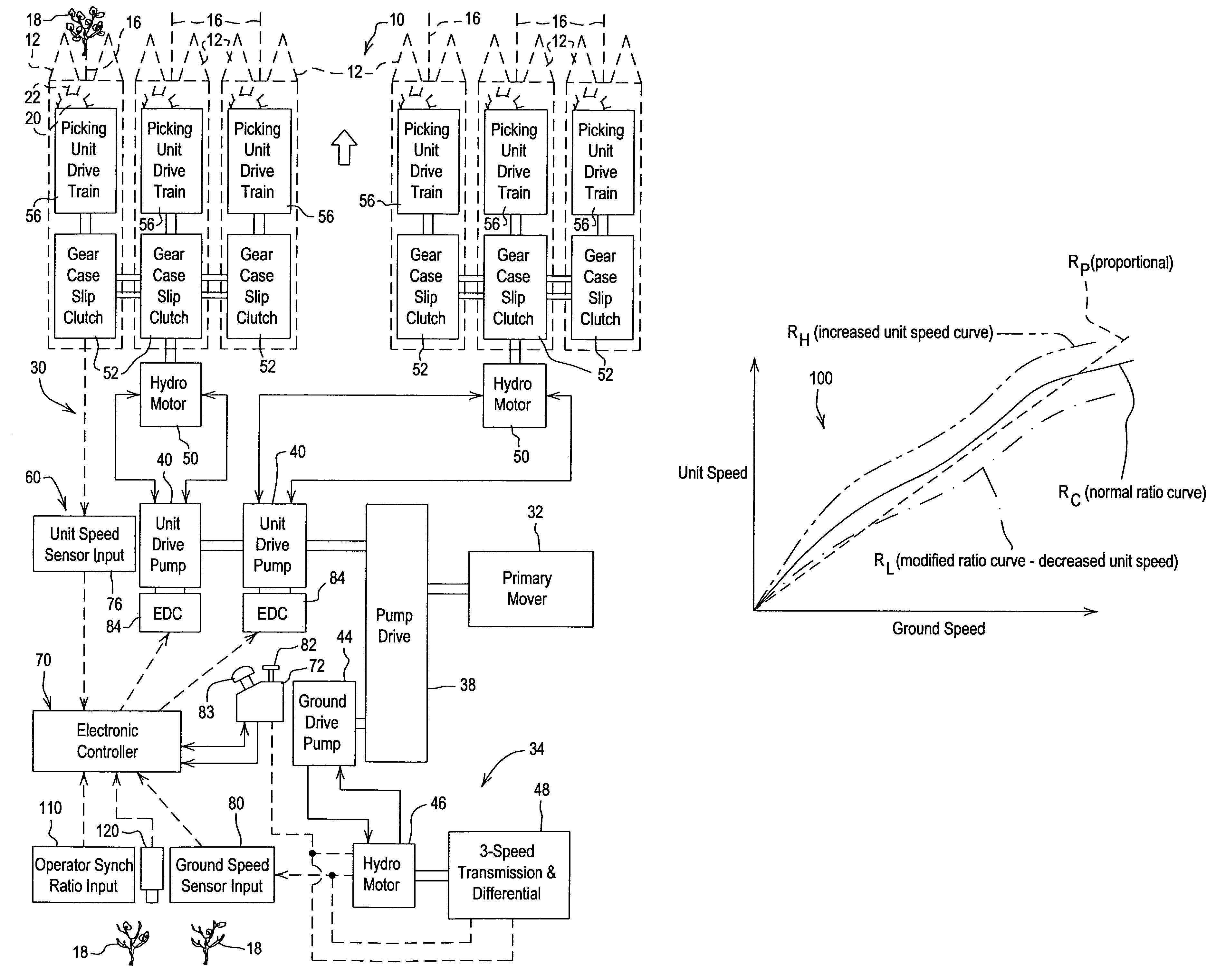
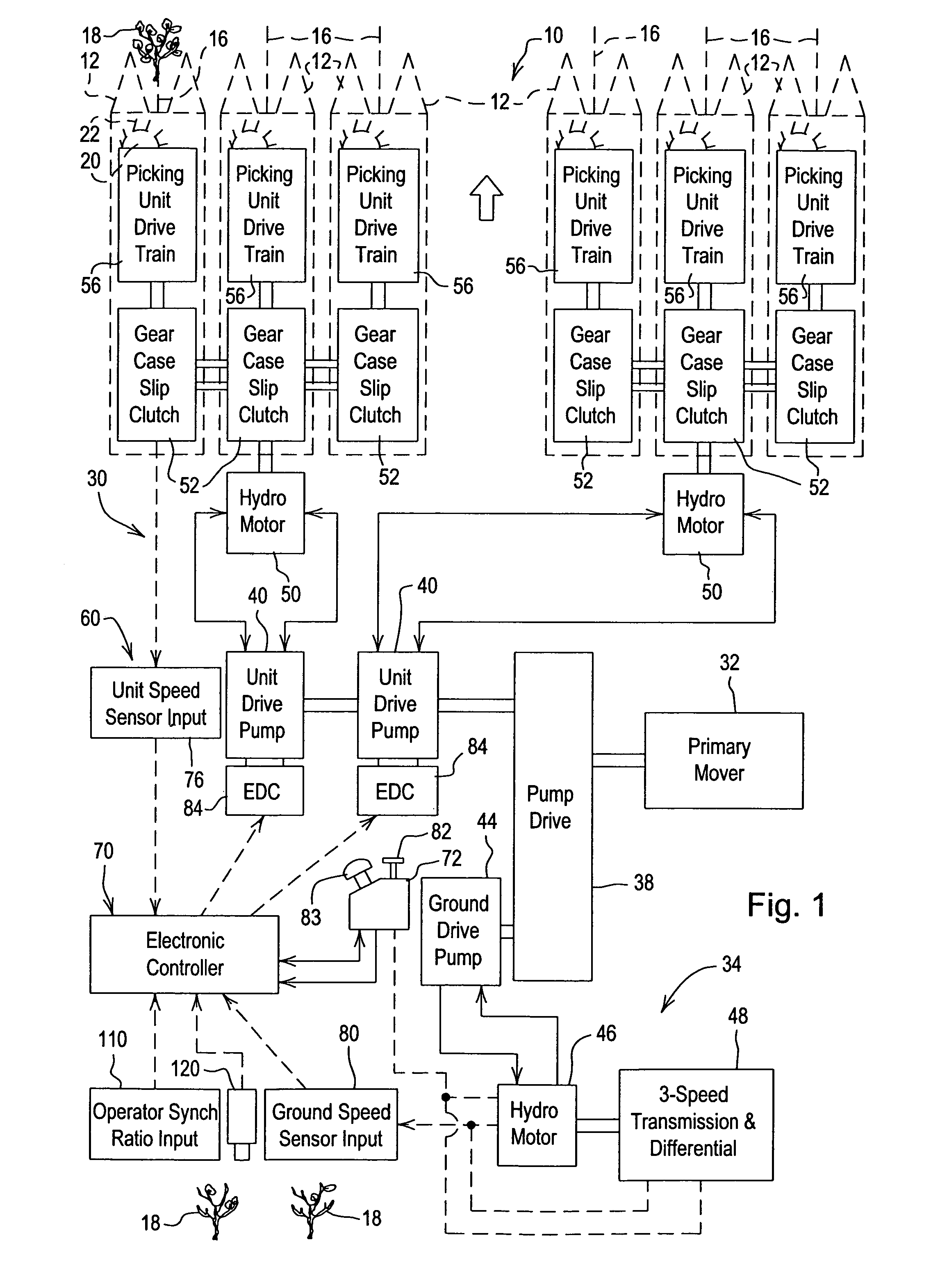
[0018]Referring to FIG. 1 therein is shown schematically portions of a cotton picker 10 including a plurality of conventional cotton harvester row units 12 transversely spaced at the forward end of the picker and including row receiving areas 16 for receiving cotton plants 18. The row units 12 include rotating cotton harvesting structure such as upright picker drums 20 with spindles 22 for entering and rotating in the row receiving areas and removing cotton from the plants 18. The drums 20 are rotated about upright drum axes and the spindles 22 are rotated about spindle axes by picking unit drive structure indicated generally at 30. Typically the rotation of the drums 20 is synchronized to the forward speed of the harvester 10 so that for a period of time, while the spindles 22 engage the cotton plant, the velocity of the spindle relative to the plant is approximately zero.

[0019]The harvester 10 includes a primary mover or engine 32 powering the drive structure 30 and as well as a g...


PUM


Abstract

An electronic controller with a sensed ground speed input calculates appropriate cotton harvester row unit speed based on harvester ground speed and a preset ground speed versus a unit speed curve. The controller includes an automatic or manual ratio adjustment input. The ratio adjustment input allows the unit speed to be increased or decreased from the preset speed. The controller reads row unit speed via unit speed sensors and sends a signal to the unit speed actuator or electronic drive control (EDC) on a hydro, variable sheave, or other variable drive device to adjust unit speed to the calculated value. A detector or field vision device such as a camera responsive to cotton on the plants provides a signal to the automatic ratio adjustment input to change the ratio for increased productivity and reduced machine wear.

Description

FIELD OF THE INVENTION [0001]The present invention relates generally to cotton harvesters and, more specifically, to row unit drive structure for such harvesters.BACKGROUND OF THE INVENTION [0002]On spindle picking cotton harvesters, the synchronization between the ground speed and the picking unit drum speed is critical to achieve optimal picking efficiency and cotton quality. Current harvesters synchronize the ground speed to unit speed using mechanical methods such as gear drives through the ground drive transmission and mechanical linkages between hydro pumps. Mechanical systems typically provide a linear relationship between ground speed and unit speed, and synchronization can only occur in one gear range. Synchronization is lost when the transmission shifts gear or the harvester is turned from the forward direction. In addition, ground speed and unit speed synchronization is lost over time because of efficiency changes; tolerance stack-up, and part wear including tire tread we...

Claims


Application Information

Patent Timeline
Patent Type & Authority Patents(United States)
IPC IPC(8): G06F19/00A01D46/08A01D69/00G06G7/48
CPCA01D46/085
Inventor BARES, ROBERT MATTHEWHAECKER, JESSE DRUMCCOY, WILLIAM EDWARDDEUTSCH, TIMOTHY ARTHUR
Owner DEERE & CO
Why Eureka
Try Eureka