Semiconductor device and method of fabricating the same
a technology of semiconductor devices and semiconductors, applied in semiconductor devices, semiconductor/solid-state device details, electrical apparatus, etc., can solve problems such as tddb failure and tddb failur
- Summary
- Abstract
- Description
- Claims
- Application Information
AI Technical Summary
Benefits of technology
Problems solved by technology
Method used
Image
Examples
first embodiment
[0050]The following paragraphs will explain a semiconductor device of the first embodiment.
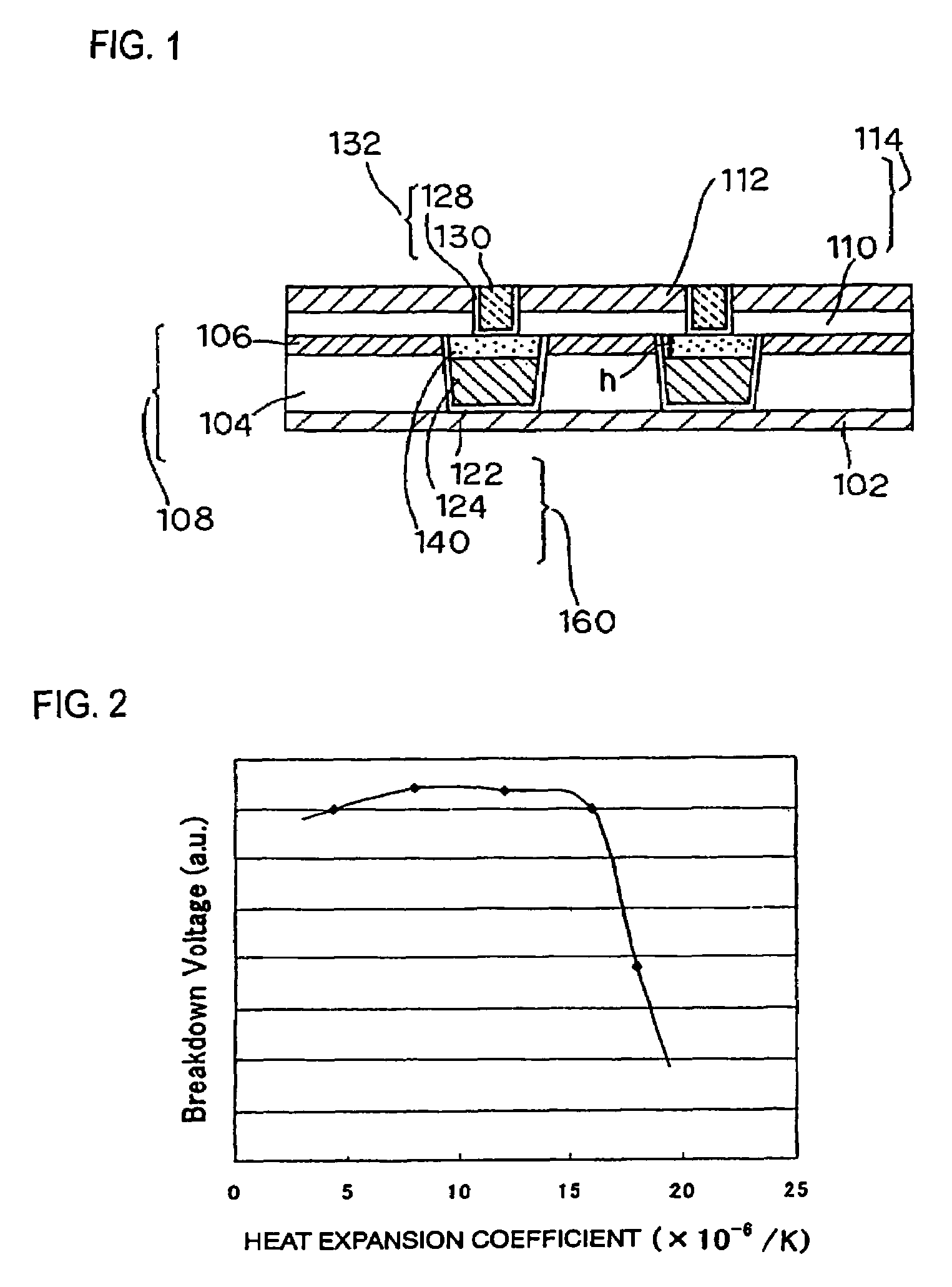
[0051]FIG. 1 is a sectional structural view showing an exemplary configuration of the semiconductor device of this embodiment. It is to be noted that the structure covering the semiconductor substrate up to the layer just below a stopper insulating layer 102 is the same as the conventional structure, and has been omitted from the illustration.
[0052]Similarly to as shown in the conventional structure, the semiconductor device has, on the stopper insulating layer 102, an insulating interlayer 108 composed of a low-k layer 104 and a hard mask layer 106. In this embodiment, a barrier metal layer 122 is formed on the bottom and side wall of the interconnect-forming grooves formed in the insulating interlayer 108, and a Cu layer 124 and a low-expansion metal layer 140 (as a metal layer), which is a metal layer having a heat expansion coefficient smaller than that of Cu, are layered in this order in ...
second embodiment
[0081]The present embodiment relates to a case in which the low-expansion metal layer is formed to a level of height above the upper surface of the hard mask layer.
[0082]A semiconductor device of the present embodiment will be explained.
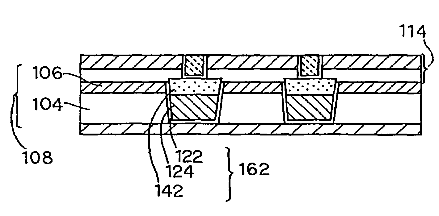
[0083]FIG. 6 is a sectional structural view showing an exemplary configuration of the semiconductor device of the present embodiment. It is to be noted that any configurations similar to those in the first embodiment will be given with the same reference numerals, omitting the explanations therefor.
[0084]An interconnects 162 in the semiconductor device of the present embodiment are configured so that a low-expansion metal layer 142 (as a metal layer) on the Cu layer 124 is formed up to a level of height higher than the upper surface of the hard mask layer 106. The low-expansion metal layer 142 partially blocks the boundary between the insulating interlayer 108 and an insulating interlayer 114. In view of preventing the resistance of the interconnect ...
third embodiment
[0091]The present embodiment relates to a case where the hard mask layer, formed on the insulating interlayer shown in the second embodiment, is omitted.
[0092]Next paragraphs will explain the semiconductor device of the present embodiment.
[0093]FIG. 8 is a sectional structural view showing an exemplary configuration of the semiconductor device of the present embodiment. It is to be noted that any configurations similar to those in the second embodiment will be given with the same reference numerals, omitting the detailed explanations therefor.
[0094]An insulating interlayer 109 of the present embodiment is configured by a low-k layer. On the low-k layer, the insulating interlayer 114 is formed without being underlain by the hard mask layer. Similarly to as described in the second embodiment, the barrier metal layer 122, Cu layer 124, and low-expansion metal layer 142 are formed in the interconnect-forming grooves, to thereby form the interconnects 162. The low-expansion metal layer 1...
PUM
| Property | Measurement | Unit |
|---|---|---|
| dielectric constant | aaaaa | aaaaa |
| distance | aaaaa | aaaaa |
| thick | aaaaa | aaaaa |
Abstract
Description
Claims
Application Information
 - R&D
- Intellectual Property
- Life Sciences
- Materials
- Tech Scout
- Unparalleled Data Quality
- Higher Quality Content
- 60% Fewer Hallucinations
Browse by: Latest US Patents, China's latest patents, Technical Efficacy Thesaurus, Application Domain, Technology Topic, Popular Technical Reports.
© 2025 PatSnap. All rights reserved.Legal|Privacy policy|Modern Slavery Act Transparency Statement|Sitemap|About US| Contact US: help@patsnap.com


