
Apparatus and method for catalytic treatment of exhaust gases

a technology of catalytic treatment and exhaust gas, which is applied in the direction of steam use, machine/engine, combustion gas purification/modification, etc., can solve the problems of reducing the nitrogen present in the flue gas to nitrogen and water only with great difficulty, and the combustion control alone may prove inadequate to satisfy the effect of net oxidizing

Active Publication Date: 2008-06-24
SIEMENS ENERGY INC
View PDF23 Cites 29 Cited by
  • Summary
  • Abstract
  • Description
  • Claims
  • Application Information

AI Technical Summary

Benefits of technology

"The patent describes a new technology for reducing harmful emissions from power plants. The technology involves using a selective catalytic reduction (SCR) process to reduce nitrogen oxides, hydrocarbons, and carbon monoxide in exhaust gases. The patent also describes a new method that combines the SCR process with a catalytic oxidizing process to further reduce emissions. The technology aims to provide a more effective solution for reducing emissions from power plants while also improving fuel efficiency."

Problems solved by technology

Thus, the oxides of nitrogen that are present in the flue gas can be reduced to nitrogen and water only with great difficulty.
The oxidizing process is typically located upstream of the ammonia injection location and upstream of the reducing catalyst because the oxidizing catalyst will also function to oxidize ammonia, which is undesirable when it decreases the amount of ammonia available for reduction of the NOx and because it produces additional NOx compounds.
Combustion controls alone may prove inadequate to satisfy these often-conflicting goals, and thus continued the improvement of post-combustion exhaust gas treatment systems is desired.

Method used


Image

  • Apparatus and method for catalytic treatment of exhaust gases
  • Apparatus and method for catalytic treatment of exhaust gases
  • Apparatus and method for catalytic treatment of exhaust gases

Examples


Embodiment Construction

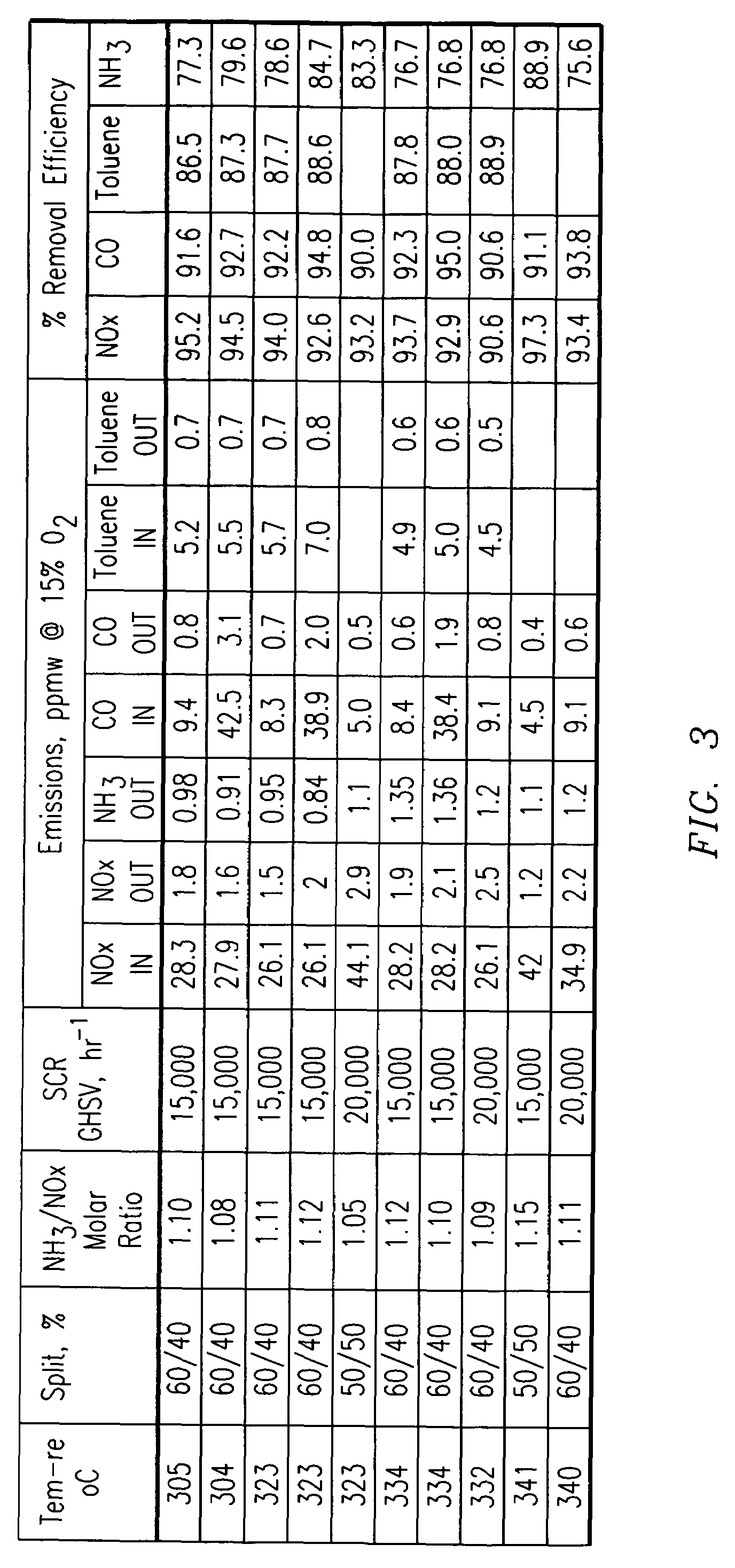
[0010]The present inventors have developed a process for the post-combustion catalytic treatment of exhaust gases that is useful in power generation applications to reduce the concentrations of oxides of nitrogen, hydrocarbons (including oxygenated hydrocarbons, such as for example aldehydes) and carbon monoxide to sub-2 ppm levels, while at the same time limiting the amount of ammonia injection that is necessary to support the incorporated SCR process and also maintaining ammonia slip to the atmosphere to below 2 ppm.

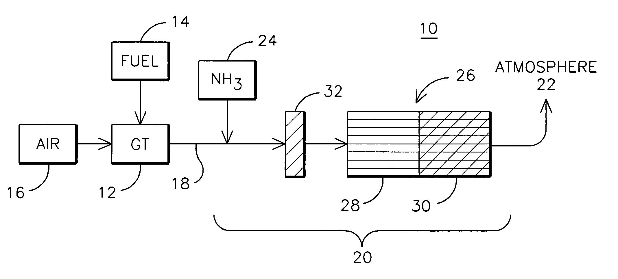
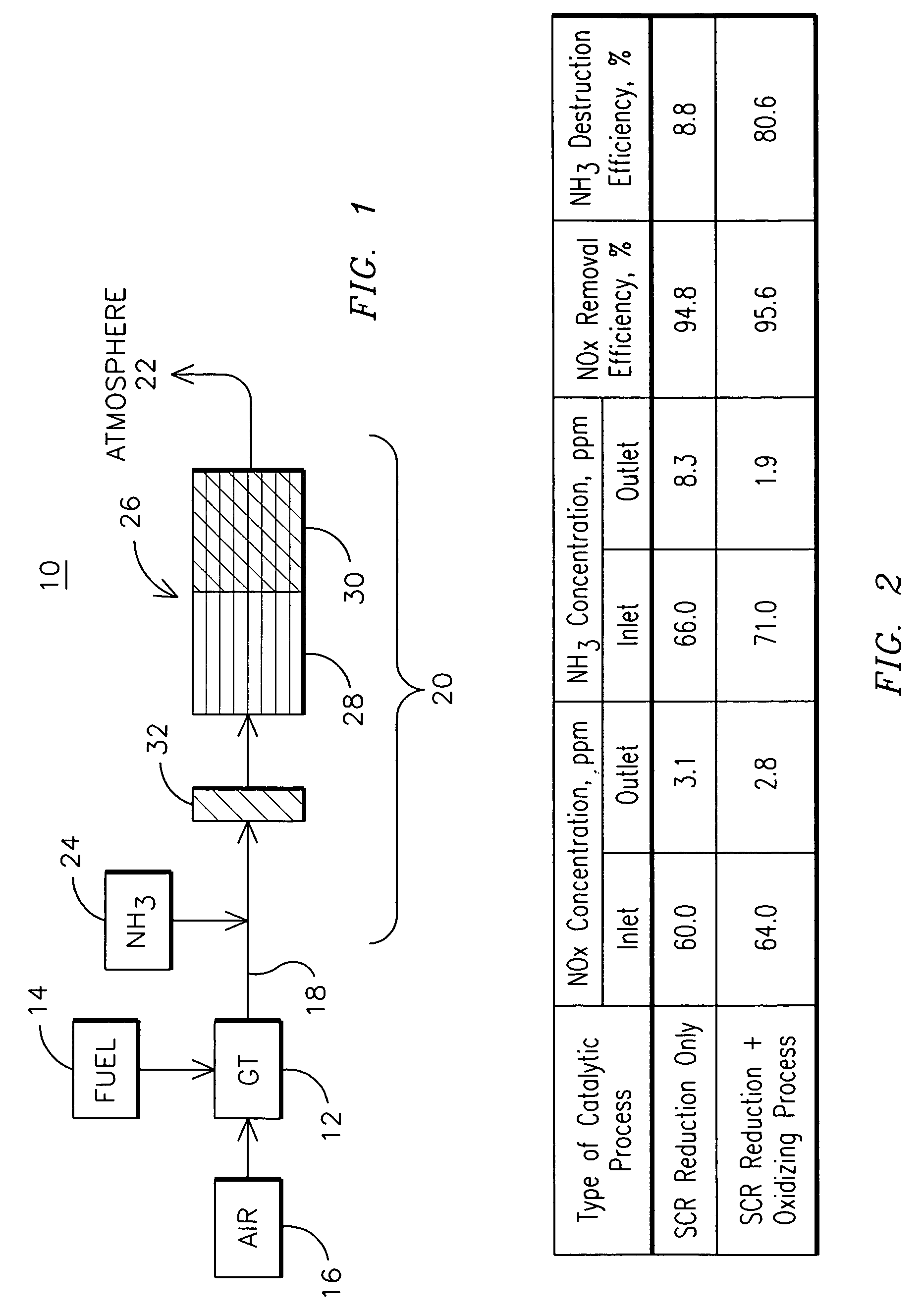
[0011]FIG. 1 is a schematic illustration of one embodiment of the present invention for a power generating plant 10 including a gas turbine engine 12 wherein energy is produced by the combustion of a hydrocarbon fuel 14 in air 16 to produce shaft power and resulting in a flow of exhaust gases 18 containing undesirably high concentrations of NOx, hydrocarbon and CO pollutants. The power generating plant 10 includes a post-combustion treatment apparatus 20 for reducing t...


PUM

PropertyMeasurementUnit
temperaturesaaaaaaaaaa
temperatureaaaaaaaaaa

Abstract

An exhaust gas treatment apparatus (20) for reducing the concentration of NOx, HC and CO in an exhaust gas stream (18) such as produced by a gas turbine engine (12) of a power generating station (10). The treatment apparatus includes a multifunction catalytic element (26) having an upstream reducing-only portion (28) and a downstream reducing-plus-oxidizing portion (30) that is located downstream of an ammonia injection apparatus (24). The selective catalytic reduction (SCR) of NOx is promoted in the upstream portion of the catalytic element by the injection of ammonia in excess of the stoichiometric concentration, with the resulting ammonia slip being oxidized in the downstream portion of the catalytic element. Any additional NOx generated by the oxidation of the ammonia is further reduced in the downstream portion before being passed to the atmosphere (22).

Description

FIELD OF THE INVENTION[0001]This invention relates generally to the treatment of a gas stream containing nitrogen oxides, for example but not limited to the gases produced by the combustion of a fossil fuel, wherein the gas stream may also contain hydrocarbons, carbon monoxide and / or ammonia.BACKGROUND OF THE INVENTION[0002]The control of undesirable emissions such as oxides of nitrogen (NOx), hydrocarbons (HC) including volatile organic compounds (VOC), and carbon monoxide (CO) that are generated by power producers such as automobiles and electrical power generating stations is a well-studied field. The Background section of U.S. Pat. No. 5,891,409 provides a useful summary of the conditions and chemistries that produce such emissions and the approaches used to limit the release of these pollutants to the environment.[0003]One technology for the control of oxides of nitrogen that is currently being used commercially at large land-based electrical power generating stations is select...

Claims


Application Information

Patent Timeline
Patent Type & Authority Patents(United States)
IPC IPC(8): B01D53/56B01D53/62B01D53/72F01N3/10F23J15/00
CPCB01D53/865B01D53/9477B01D2251/2062B01D2255/1021B01D2255/1023B01D2255/20723B01D2255/20761
Inventor SOBOLEVSKIY, ANATOLYROSSIN, JOSEPH A.
Owner SIEMENS ENERGY INC
Learn More