Fuel cell and process for the production thereof

Inactive Publication Date: 2008-06-24
SEIKO EPSON CORP
View PDF5 Cites 7 Cited by
  • Summary
  • Abstract
  • Description
  • Claims
  • Application Information

AI Technical Summary

Benefits of technology

[0036]In accordance with this process for the production of a fuel cell, first and second gas flow paths the width of which gradually decreases from the upper portion toward the bottom thereof are formed using a gas flow path-forming mold in a gas flow path-forming material, such as photo-setting resin. Accordingly, the use of a gas flow path-forming mold makes it possible to form a gas flow path having a desired shape easily and rapidly.
[0037]The process for the production of a fuel cell accord

Problems solved by technology

Further, a step of disposing the particulate carbon in the gas flow path is that disadvantageously adds to the number of steps required to produce the fuel cell.
However, since most machines for use in semiconductor process are expensive, the use of these machines increases the production cost.
In the case where a gas flow path is formed on the substrate using MEMS, it is necessary that a job of contact-bonding an electrolyte membrane to the substrate be separately effected after the formation of the gas flow path in the substrate, which complicates the production procedure.
Therefore, the supplied amount of the reactive gas varies from upstream to downstream, causing the deterioration of the electrici

Method used


Image

  • Fuel cell and process for the production thereof
  • Fuel cell and process for the production thereof
  • Fuel cell and process for the production thereof

Examples


first embodiment

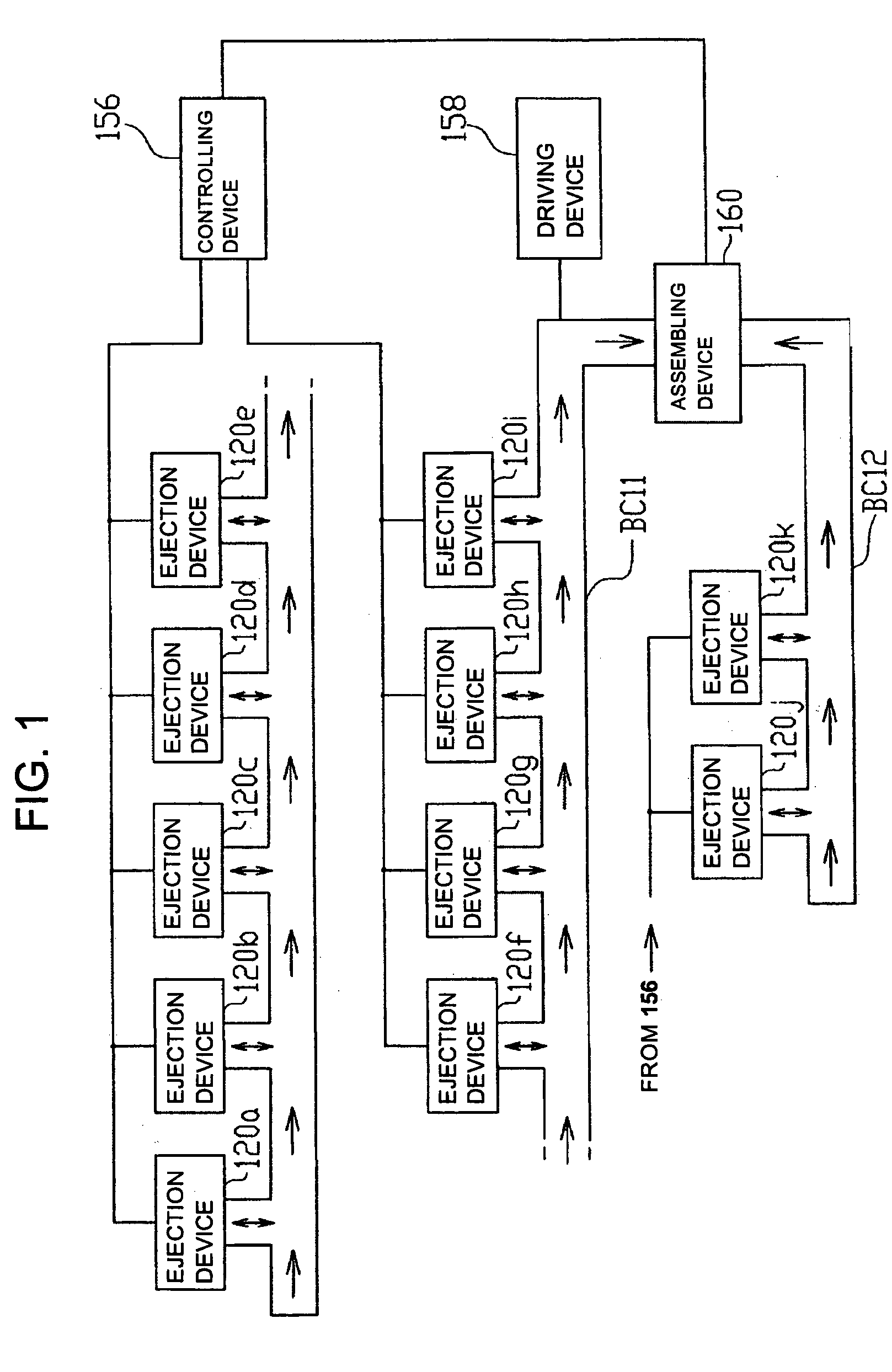
[0083]Processes for the production of a fuel cell according to embodiments of implementation of the invention will be described hereinafter. FIG. 1 is a diagram illustrating the configuration of an exemplary fuel cell production line for executing the process for the production of a fuel cell according to implementation of the invention. As shown in FIG. 1, the fuel cell production line is formed by ejection devices 120a to 120k used in various steps, a belt conveyor BCl 1 connecting the ejection devices 120a to 120i to each other, a belt conveyor BC12 connecting the ejection devices 120j and 120k to each other, a driving device 158 for driving the belt conveyors BC 11 and BC 12, an assembling device 160 for assembling a fuel cell and a controlling device 156 for controlling the entire fuel cell production line.

[0084]The ejection devices 120a to 120i are arranged at a predetermined interval in a line along the belt conveyor BC11. The ejection devices 120j and 120k are arranged at a ...

second embodiment

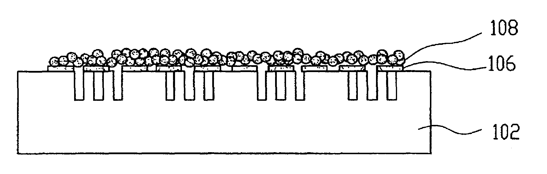
[0126]In accordance with the process for the production of a fuel cell according to implementation of the invention, a gas flow path the opening width of which is smaller than the particle diameter of particulate carbon constituting the gas diffusion layer is formed using an ink jet type ejection device. That is, a negative-working resist and a positive-working resist are ejected onto the substrate at the respective predetermined positions to form a sacrifice layer from which only the positive-working resist is then removed to form a gas flow path having a trapezoidal section. Accordingly, the particulate carbon constituting the gas diffusion layer enters in the gas flow path, making it possible to prevent the clogging of the gas flow path.

[0127]Further, a gas flow path having a trapezoidal section, i.e., gas flow path the opening width of which is smaller than the particle diameter of particulate carbon constituting the gas diffusion layer and the bottom width of which is greater t...

third embodiment

[0135]A process for the production of a fuel cell using gas flow path forming devices 214a and 214b and ejection devices 220a to 220g according to implementation of the invention will be described hereinafter in connection with the flow chart of FIG. 18 and other attached drawings.

[0136]Firstly, a gas flow path for supplying a reactive gas is formed in the substrate (Step S20). That is, a rectangular flat substrate 202 made of, e.g., silicon (first substrate) as shown in FIG. 19(a) is conveyed to the ejection device 214a by the belt conveyor BC21. The surface of the substrate 202 which has been conveyed by the belt conveyor BC21 is then coated with a resin 204, e.g., photo-setting or thermosetting resin (see FIG. 19(b)). Actually, the surface of the substrate 202 is coated with an uncured low viscosity resin 204, e.g., resin 204 having a viscosity of about 20 mPa·s.

[0137]Subsequently, a gas flow path forming mold which has been previously prepared is pressed against the resin 204 so...


PUM


Abstract

A first gas flow path is formed in a first substrate. The first substrate is processed in an ejection device to form a first collector layer, a first gas diffusion layer, a first reactive layer, and an electrolyte membrane. Similarly, the first substrate is processed to form a second reactive layer, a gas diffusion layer, and a second collector layer. A second substrate which has been processed to form a second gas flow path is then disposed on the first substrate to complete production of a fuel cell having a gas flow path formed therein the opening width of which is smaller than the particle diameter of the material constituting the gas diffusion layer.

Description

BACKGROUND OF THE INVENTION[0001]1. Field of Invention[0002]The present invention relates to a fuel cell which undergoes reaction of various kinds of reactive gases supplied into the respective electrodes to generate electricity and a process for the production thereof.[0003]2. Description of Related Art[0004]Heretofore, there have been fuel cells including an ion-permeable electrolyte provided interposed between porous electron-permeable electrodes. Among these fuel cells are those which use hydrogen, natural gas, alcohol or the like as a fuel to generate electricity. Among these fuel cells, the fuel cell which uses, for example, hydrogen as a fuel receives a first reactive gas containing hydrogen in one electrode and a second reactive gas containing oxygen in the other electrode to generate electricity by the reaction of the hydrogen contained in the first reactive gas with the oxygen contained in the second reactive gas.[0005]The substrate of the fuel cell has a gas flow path for...

Claims


Application Information

Patent Timeline
IPC IPC(8): H01M8/04H01M8/10B05D5/12H01M4/86H01M4/94H01M8/00H01M8/02
CPCH01M8/0228H01M8/0265H01M8/0258H01M8/0247Y02E60/50Y02P70/50H01M8/02H01M8/241
Inventor YAMADA, SHUHEIMIURA, HIROTSUNAYAMAZAKI, YASUNORIAJIKI, YOSHIHARU
Owner SEIKO EPSON CORP
Why Eureka
Try Eureka