Integrated filter connector

a filter connector and integrated technology, applied in the direction of coupling device connection, two-pole connection, two-part coupling device, etc., can solve the problems of reducing the opportunity of rf ingress, omission or removal of these devices, and reducing the possibility of rf ingress, so as to reduce the potential for rf ingress and eliminate the connection

Inactive Publication Date: 2008-07-01
PPC BROADBAND INC
View PDF29 Cites 116 Cited by
  • Summary
  • Abstract
  • Description
  • Claims
  • Application Information

AI Technical Summary

Benefits of technology

[0006]It is therefore a desired object of the present invention to provide an integrated filter connector that performs the functions of a coaxial cable connector component combined with the functions of an in-line signal conditioning component. Elimination of a connection (coupling) between a coaxial cable connector component and a fitting on a typical in-line conditioning device component will result in reducing the potential for RF ingress into a signal path traveling through the integrated filter connector.
[0007]The advantages of incorporating an in-line device with a cable connector are not limited to regulating usage by the installers. Other advantages that become evident include elimination of ground contact points (as compared with a filter and connector that are joined conventionally) and moisture entry points, as well as reduced length, as compared with a non-integrated filter and connector.

Problems solved by technology

The ingress of RF energy is known to be a substantial factor in the degradation of the quality of the signals passed in each direction in a CATV network.
Each connection (coupling) between a coaxial cable and the equipment in the distribution network is a potential point of ingress of RF energy that may interfere with the network signals.
Consequently, reducing the number of connectors and splices and improving the quality of the connections (couplings) between coaxial cable and distribution equipment reduces the opportunity of RF ingress.
In fact and in many instances, it is a general desire of the system operator to ensure that line conditioning devices are used and to make omissions or removal of these devices difficult for the installer.

Method used


Image

  • Integrated filter connector
  • Integrated filter connector
  • Integrated filter connector

Examples


first embodiment

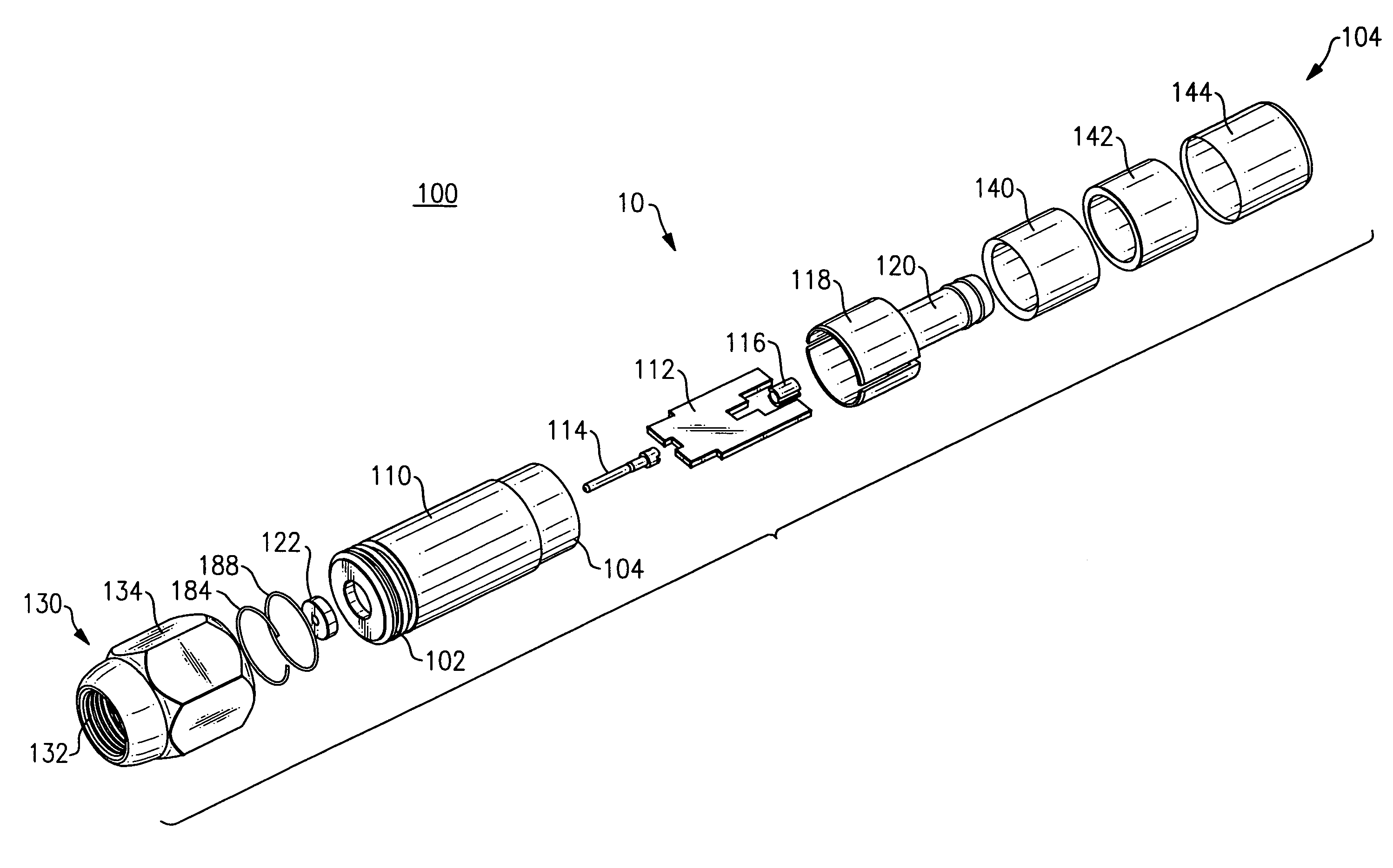
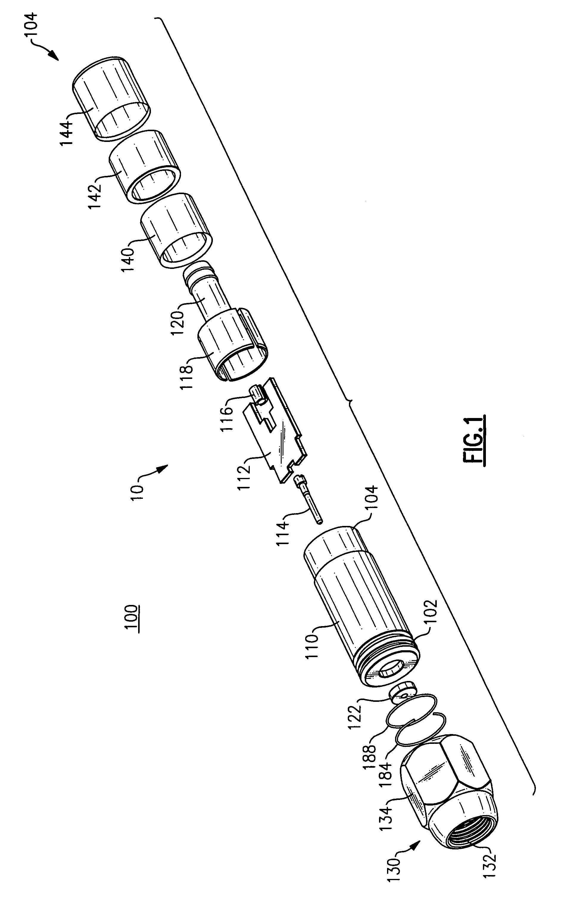
[0028]FIG. 1 is an exploded perspective view of an unassembled integrated filter and connector assembly 10 made in accordance with the present invention. As shown, the integrated filter and connector assembly 10, also referred to as an integrated filter connector 10, includes a connector body 110 having a front body end (forward end) 102 and a rear body end (rear end) 104, which is configured to enclose an electric circuit which in one form can be a printed circuit board (PCB) 112 that performs in-line signal conditioning and that functions as part of an integrated signal filter assembly.

[0029]As assembled within the outer body 110, a post 120, including an attached circuit board support 118, is configured to receive and to provide mechanical support to the circuit board 112. The circuit board support 118 is constructed as a circular shaped member and includes slots 118a and 118b. The slots 118a and 118b are disposed at opposing locations along a circumference of the circular shaped...

second embodiment

[0052]In this second embodiment, the compression member 142 is surrounded by the rotatable housing member 452. Like the sliding housing member 144, the rotatable housing member 452 includes an inward flange 446 at its rear end 104. The inward flange 446 radially surrounds at least a portion of the compression member 142.

[0053]A forward end of the rotatable housing member 452 includes an interior threaded surface 454 that is configured to engage an exterior threaded surface 456 disposed at the rear end 104 of the outer body 410. Rotation of the housing member 452 axially advances over the exterior threaded surface 456 and towards the front end 102 of the outer body 410.

[0054]Axial advancement of the rotatable housing member 452 towards the front end 102 advances the compression member 142 into the inner sleeve 140 to cause inward radial deformation of the compression member 142 against the outer layers of a coaxial cable that is inserted into the internal bore 450 and engaged with th...

ninth embodiment

[0102]As assembled, the filter body 1410 is capped by header 1424, also referred to as a rear header 1424. The header 1424 is press fit into the open rear end of the filter body. The header 1424 may include a groove to seat a first O-ring seal 1488a. Opposing longitudinal slots 1482a and 1482b (not shown) are positioned to receive and support the sides of the PCB 112. The ground plane of the circuit board 112 may be electrically engaged by the longitudinal slots 1482a-1482b in the header 1424. The header 1424 has an inner surface defining a central throughbore. The inner surface includes an internal groove 1475 for the partial seating of the locking member 1422. The inner surface of the header 1424 may also be configured to receive the rear insulator 1178. The inner surface of the header 1424 is also configured to receive a post 1420 which is configured and operates in the same manner as post 1120 in the ninth embodiment described above.

[0103]A locking member 1422 is similarly dimen...


PUM


Abstract

An integrated filter connector apparatus that performs the functions of a coaxial cable connector component combined with the functions of an in-line signal conditioning component. The apparatus eliminates at least one exposed point of connection between a separate coaxial cable connector component and an in-line signal conditioning component. Elimination of such a point of connection likely reduces RF ingress into a signal path and likely reduces interference with a signal traveling through the signal path. Embodiments of the connector apparatus provide various types of connector interfaces.

Description

FIELD OF THE INVENTION[0001]This patent application is related to the field of cable connectors and in particular to an integrated filter connector that performs the functions of a coaxial cable connector component combined with the functions of an in-line signal conditioning component.BACKGROUND OF THE INVENTION[0002]CATV systems presently utilize a wide range of in-line filters, traps, attenuators, and other line conditioning equipment. The line conditioning equipment is used to maintain or improve the quality and to control the content of the network signal to an individual subscriber's premises. Conversely, the above equipment is also used in order to maintain, protect or condition the signals generated by devices within the subscriber's premises location and returned to the CATV network.[0003]The ingress of RF energy is known to be a substantial factor in the degradation of the quality of the signals passed in each direction in a CATV network. Each connection (coupling) between...

Claims


Application Information

Patent Timeline
Patent Type & Authority Patents(United States)
IPC IPC(8): H01R13/66
CPCH01R24/42H01R13/719H01R13/6658H01R2103/00
Inventor PALINKAS, RAYMONDMONTENA, NOAH
Owner PPC BROADBAND INC
Why Eureka
Try Eureka