
Formulation suitable for ink receptive coatings

a technology of ink receptive coating and formulation, which is applied in the direction of synthetic resin layered products, natural mineral layered products, thermal imaging, etc., can solve the problems of coating suffering from the shortcoming of relatively long ink dry time, no longer continuous binding phase, and insufficient binder to fill the gaps, etc., to achieve good ink absorption properties, high gloss finishes, and internal porosity of particles

Inactive Publication Date: 2008-07-01
WR GRACE & CO CONN
View PDF85 Cites 15 Cited by
  • Summary
  • Abstract
  • Description
  • Claims
  • Application Information

AI Technical Summary

Benefits of technology

The invention is about a new type of binder and particles made of porous inorganic oxide. These particles have a unique structure with small pores that make them stable and less susceptible to collapsing under pressure. The particles can be coated onto substrates and dried to form a layer that absorbs ink well, making it suitable for printing. The resulting layer has a high gloss finish. The particles can also be used to make high-quality finishes for photorealistic printing.

Problems solved by technology

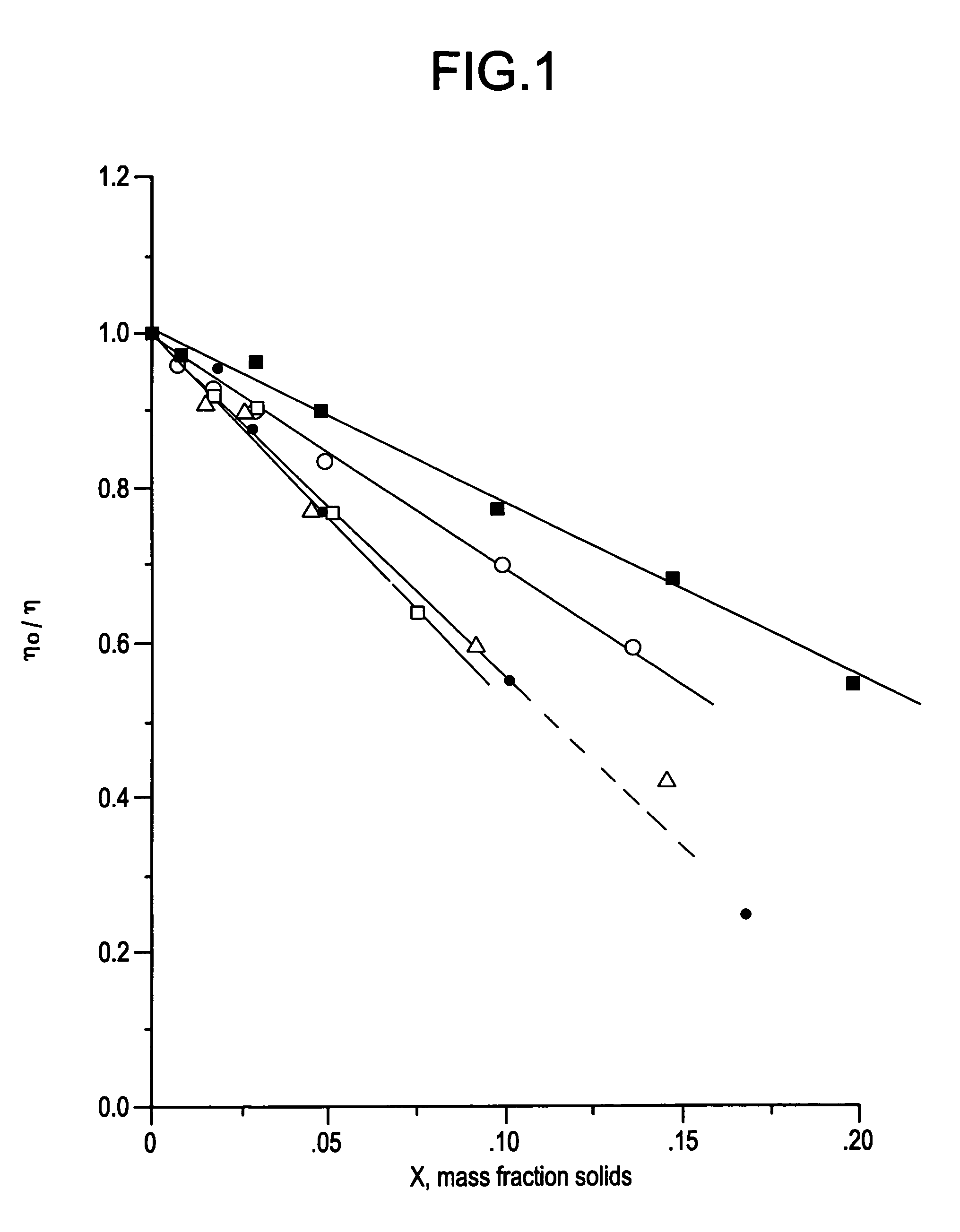
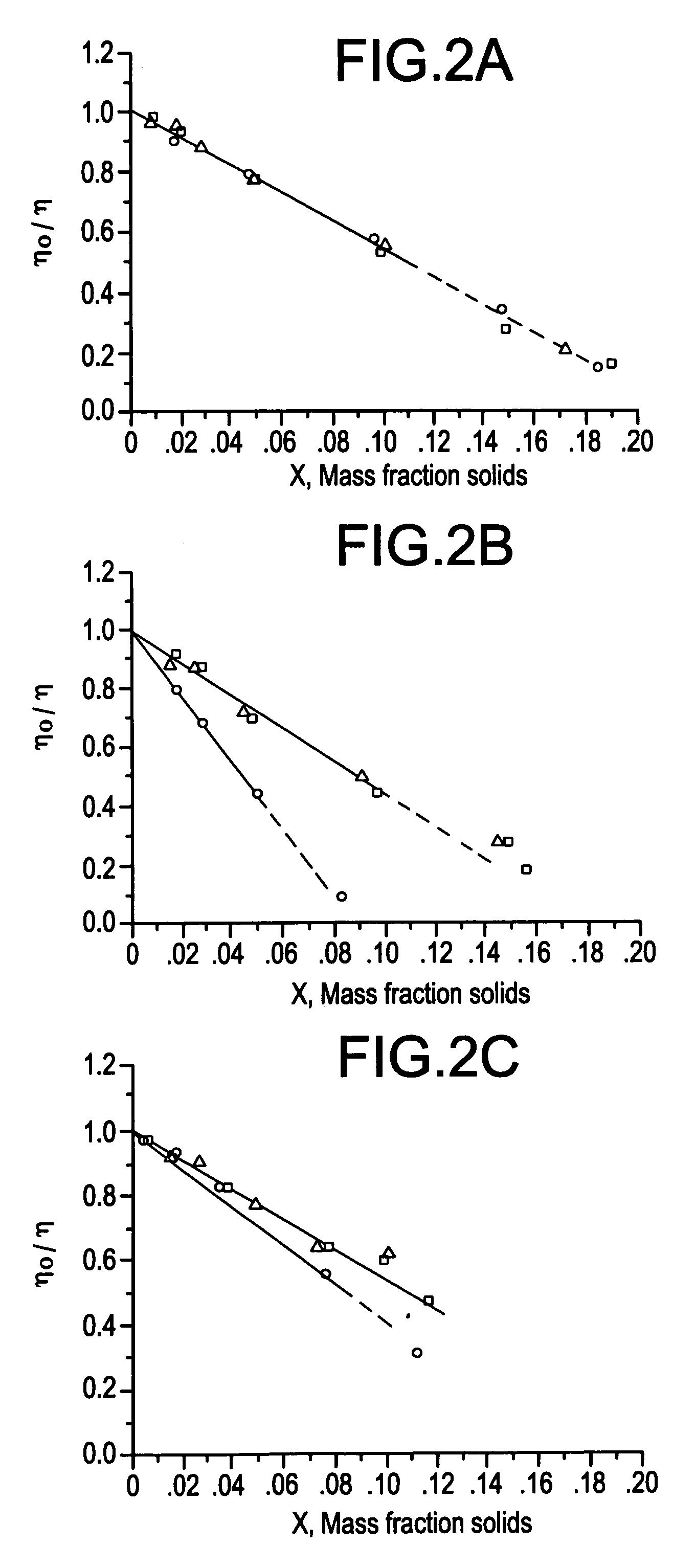
When a coating is formulated at high PVC, the binder phase is no longer a continuous phase, that is, there is not enough binder to fill the voids between packed and semi-rigid or rigid pigment particles.
However, unless the binder is hygroscopic, such coatings will be relatively impermeable to water.
For an ink-jet printing application with aqueous inks, such a coating would suffer from the shortcoming of relatively long ink dry-time.
These formulations generally result in relatively glossy coatings and the hygroscopic binders absorb moisture via partial solubility of the ink-fluid.
However, colloidal silica is non-porous and coatings prepared from colloidal silicas are relatively dense.
Such a coating therefore lacks capacity to absorb large quantities of liquid ink.
Furthermore, ink-drytimes are relatively slow.
At high PVC, a network of interstitial void space, or pores between the particles, is created by imperfect packing of the particles and the lack of a suitable amount of binder to fill the interstitial voids.
However, the gloss of such coatings is usually relatively low because the surface exhibits a degree of roughness that is related to the pigment particle size.
Colloids derived from fumed silica also have been used for this purpose, but those materials are also non-porous.

Method used


Image

  • Formulation suitable for ink receptive coatings
  • Formulation suitable for ink receptive coatings
  • Formulation suitable for ink receptive coatings

Examples


example i

Silica Gel Particles Derived from Hydrogel Parent

[0110]Well drained hydrogel1 was presized by a Prater mill to a median particle size of approximately 30μ. The powder was then slurried in deionized water (DI) yielding a slurry of about 20% by weight solids and pH of about 8. This slurry was fed to a five (5) liter Drais media mill (model PM5RLH, 1.5 mm, glass media) at a rate of one liter per minute resulting in a viscous slurry. 1Hydrogel prepared at about 1.5 pH to produce 19% by weight silica and washed with dilute NH4OH.

[0111]Separation of the coarse and fine (submicron) fractions of the milled silica gel product was accomplished by a two step centrifugation process (90 min. at 1400 G's, decant, then 40 min. at 2,000 G's). The final submicron particle suspension was obtained by simply decanting. The solids content of the supernatant dispersion was 13 wt. % and yield was determined to be 41% (on a dry SiO2 basis).

[0112]

Particle Size Distribution (Horiba 900)2  10%.13μ  50%.22μ  9...

example ii

Silica Gel Particles Derived from Hydrous Gel Parent

[0113]Another submicron silica gel product was made using the same process as described in Example I except that the parent gel was presized in an air classification mill yielding a median silica gel particle of approximately 15μ. The gel is partially dried during this process with its moisture content (measured as total volatiles) dropping from about 67% to 55% by weight thus forming a hydrous gel material.

[0114]After media milling and centrifugation as described in Example I (except at 27% solids vs. 20% in Ex. I), a supernatant comprising a dispersion of 12 wt. % solids at a yield of 10% was obtained. The supernatant had the following particle size distribution:

[0115]

Particle Size Distribution (Horiba 900)  10%.13μ  50%.18μ  90%.30μ99.9%.55μ

example iii

Silica Gel Particles Derived from Aerogel Parent

[0116]Wet-milled Genesis™ gel was slurried to approximately 20% solids by weight in deionized water and the pH was adjusted to about 8. The slurry was then wet milled using a Netzsch LMZ-11 mill (with 0.6-0.8 mm SEPR media) at 3.8 liters per minute. The milled slurry was then diluted to 14.9% solids with DI water using a Myers mixer.

[0117]Separation of the coarse and fine fractions of the milled gel was accomplished by a two step centrifugation process, i.e., 90 minutes at 1,050 G's, decant, then another spin at the same conditions.

[0118]The total solids was 8.8% and the particle size distribution was:

[0119]

Particle Size Distribution (Horiba 900)  10%.086μ  50%.121μ  99%.181μ99.9%.322μ


PUM

PropertyMeasurementUnit
particle sizeaaaaaaaaaa
zeta potentialaaaaaaaaaa

Abstract

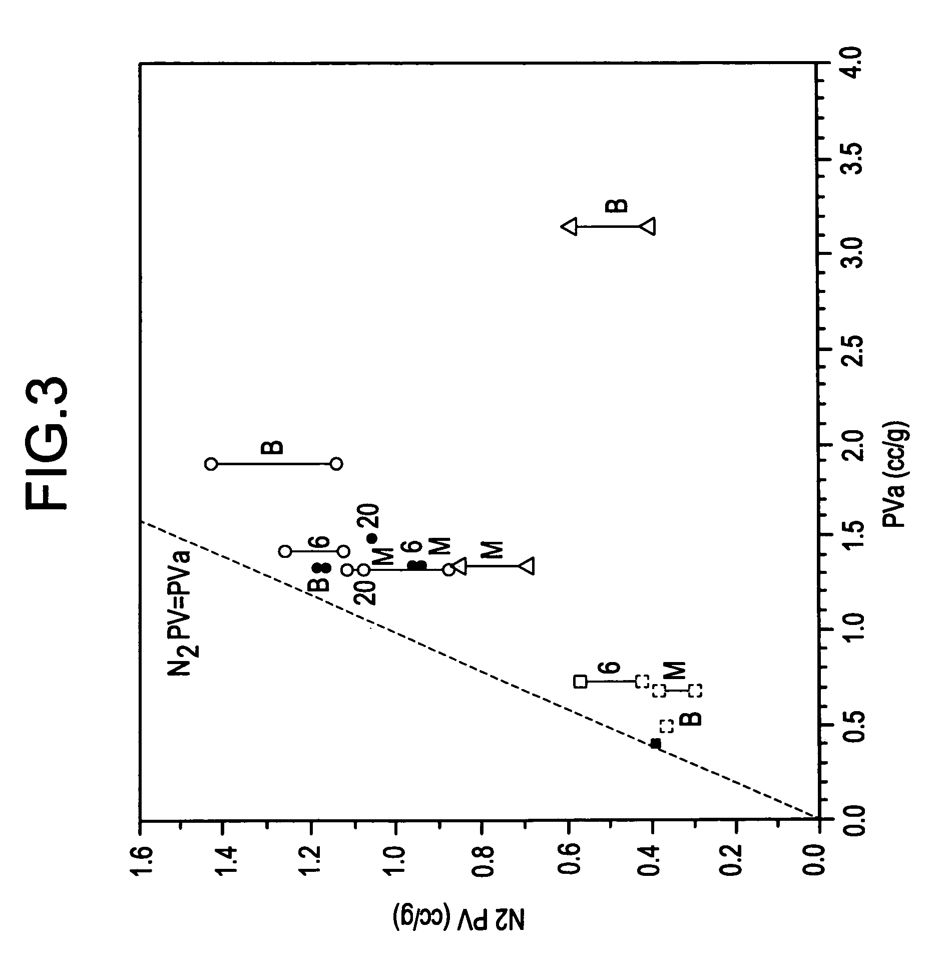
Formulations comprising novel porous metal oxide particles and binder are particularly suitable for ink receptive coatings, e.g., for ink jet papers and films. The metal oxide particles used in this application have a porous structure that differs significantly from the nonporous silica colloids. The particles have a median particle size in the range of about 0.05 to about 3 microns and porosity such that when an aqueous dispersion of the particles is dried at least 0.5 cc / g of pore volume is from pores having a pore size of 600 Å or less. The particles also have a viscosity derived pore volume of at least 0.5 cc / g.

Description

[0001]This is a divisional application of Ser. No. 10 / 305,041, filed Nov. 26, 2002 now U.S. Pat. No. 6,780,920, which is a divisional application of Ser. No. 09 / 112,540, filed Jul. 9, 1998 now U.S. Pat. No. 6,841,609.BACKGROUND OF THE INVENTION[0002]This invention relates to formulations comprising inorganic oxide particles. In particular, this invention relates to ink receptive coating formulations for paper comprising a novel porous, fine inorganic oxide which provides excellent ink absorption properties, and if desired, glossy finishes.[0003]Ink receptive coatings typically contain various proportions of inorganic pigments and binder(s). The proportions of these components affect the properties of these coatings, e.g., ink absorption properties. One means of characterizing the proportion of inorganic pigment relative to the proportion of binder is by the pigment volume concentration, or PVC. The definition of pigment volume concentration (PVC) is: 100*Vp / (Vp+Vb), where Vp is the ...

Claims


Application Information

Patent Timeline
Patent Type & Authority Patents(United States)
IPC IPC(8): B41M5/40B41M5/00B41M5/50B41M5/52C08K3/00C08K3/36C08K9/02C08L101/00
CPCB41M5/5218C08K3/0008C08K3/36C08K9/02B41M5/52C08L57/12C08L29/04C08L31/04Y10T428/2982B41M5/5245B41M5/5254C01P2004/61C01P2004/62C01P2006/14B41M5/5236Y10T428/253Y10T428/256C08K3/01Y10T428/249956Y10T428/249953B41M5/50C08K3/00
Inventor CHAPMAN, DAVID MONROEMICHOS, DEMETRIUS
Owner WR GRACE & CO CONN
Learn More