Interferometer-type radar

a radar and interferometer technology, applied in the field of interferometer-type radars, can solve the problems of ambiguity, large number of beams, and extremely small time window for receiving time, and achieve the effects of improving s/n ratio, high reliability, and easy realization of low pri

Inactive Publication Date: 2008-07-01
NEC CORP
View PDF11 Cites 16 Cited by
  • Summary
  • Abstract
  • Description
  • Claims
  • Application Information

AI Technical Summary

Benefits of technology

[0019]In the present invention, transmitting signals are not pulses but CW or FMCW signals, which is different from a typical radar, so it is possible to use transmitting modules for general communications not for a radar. Therefore, it is possible to easily realize low price and high reliability. Further, since CW or FMCW is used, S / N ratio is improved by long-hour integration, whereby transmitting power required for imaging may be significantly smaller comparing with a conventional radar. Further, it is possible to realize much higher sensitivity than a conventional radar. Therefore, a small size and low price can be realized.
[0020]An interferometer-type radar device has been realized in the astronomical field for observing stars and the sun. In such systems, the device detects slight energy generated by a target itself, and creates a radiation map. In these systems, it has not been necessary to measure distance to the target. On the other hand, in order to monitor missiles or aircrafts, not only velocity but also distance is very important information. Further, energy emitted from an aircraft or a missile itself is unknown, so it is not used for imaging.
[0021]On the other hand, in the present invention, electromagnetic wave energy required for imaging is emitted from a transmitter. Since FMCW signals are used as transmitting signals, distance information can be obtained by converting distance information to frequency information. A target in the whole illuminating area can be imaged for every certain time, without scanning the beam of the transmitting antenna.
[0022]Further, since CW signals are used as transmitting signals, it is possible to obtain the velocity of the target easily by analyzing spectrum of baseband signals. The velocity resolution is determined depending on the Doppler frequency resolution, and determined by the number of data of FFT. Even for a target moving at a very high speed such as a missile or an ICBM, it is possible to obtain the resolution easily by analyzing with FFT of the Doppler frequency.
[0023]In a conventional FMCW radar, it was difficult to range a target moving at a high speed with high sensitivity and high accuracy. However, in the high-accuracy ranging mode of the present invention, by correcting receiving data and performing time integration within a range where a target is seemed to perform uniform linear motion, by using velocity data of the target obtained in the MTI mode, it is possible to perform distance measurement with high sensitivity and high accuracy the same as a pulse radar.
[0024]The transmitter is composed of a plurality of small transmitting modules, and by adjusting phase shifters, it is possible to easily change the beam from a pencil beam to a broad beam. It is possible to concentrate the transmitting power in a specific target direction, to improve S / N ratio of receiving signals, and to perform imaging by ISAR processing.

Problems solved by technology

Therefore, there is a case where a target, in which the radar cross section area for reflecting the transmitting signal is small, cannot be found.
In a case that the target is a flying object moving at an extremely high speed such as a missile, the receiving time window becomes extremely small, whereby ambiguity is caused in the distance measurement.
However, since there is a limit in the number of beams capable to be divided, the number of target which can be tracked is limited.
However, when the target is moving, there is a problem that a baseband signal, which is a frequency-converted receiving signal by a transmitting signal, is affected by a Doppler shift due to the velocity of the target, and at the same time, the frequency changes according to the movement of the target, whereby it is impossible to measure the distance accurately.
Further, if the velocity and a change in the velocity of the target are large, or if there are a number of targets of different velocities at the same time, it is difficult to apply the above-mentioned method.
Therefore, when measuring a long distance, there is a problem that a fast repetition cycle cannot be adopted, whereby it is difficult to measure the distance to a target moving at a high speed with higher accuracy.

Method used


Image

  • Interferometer-type radar
  • Interferometer-type radar
  • Interferometer-type radar

Examples


Embodiment Construction

[0034]Hereinafter, the present invention will be explained in detail based on the drawings.

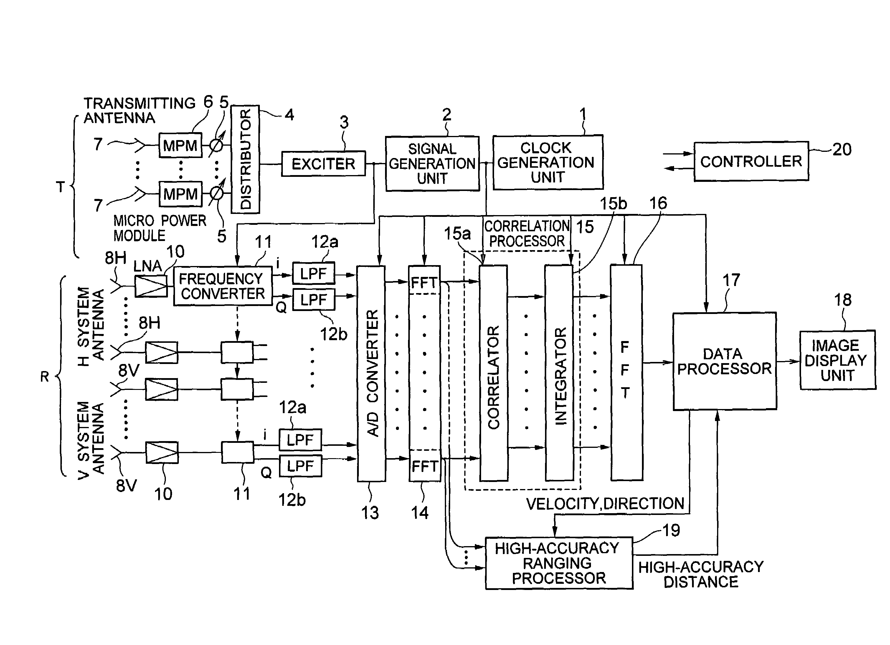
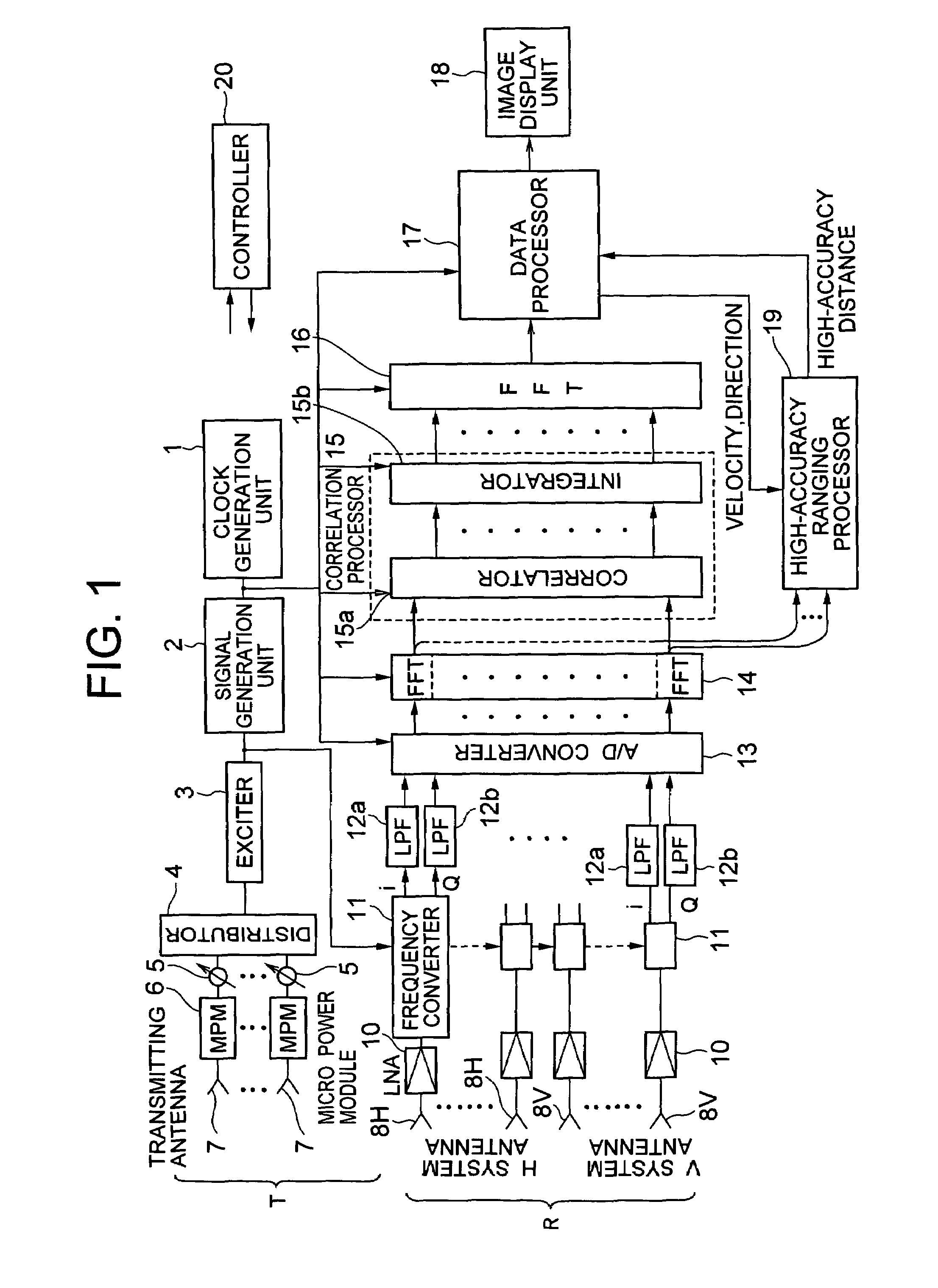
[0035]As shown in FIG. 1, an interferometer-type radar according to the embodiment of the present invention includes: a transmitter T consisting of a plurality of transmitting modules; and a plurality of receivers R.

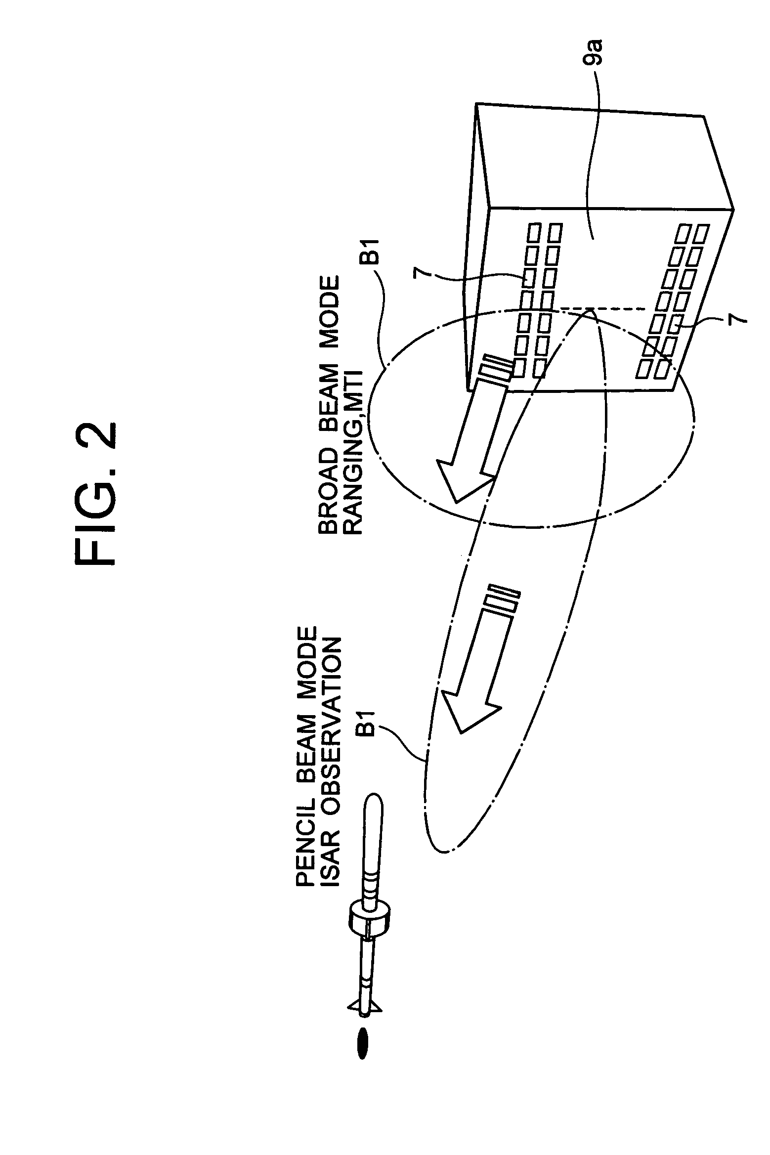
[0036]When viewed from the operational side, the interferometer-type radar according to the embodiment of the present invention shown in FIG. 1 has two operational modes, that is, a passive mode and an active mode. The active mode includes a ranging mode, an MTI mode, a high-accuracy ranging mode and an ISAR mode. Each mode will be explained.

[0037]The passive mode is an operational mode in which directions and radio signal intensity of all radio signal sources in a receivable frequency range within receiving antenna beams, such as signals of a meteorological radar of an aircraft, an FCS radar of a fighter, and a radar mounted on a satellite, are displayed without emitting radio sig...


PUM


Abstract

A transmitter for transmitting signals to targets and a receiver for receiving signals reflected from targets are included. The transmitter outputs CW signals for detecting direction and velocity of the target. The receiver performs: a function of receiving signals reflected from targets with a plurality of receiving antennas at the same time as transmitting from the transmitter, and performing spectral analysis with respect to receiving signals to thereby classify them by velocity component; a function of correlating signals of the receiving antenna systems; a function of integrating the signals correlation-processed; and a function of obtaining phase fronts of signals made incident on an antenna face from the phase differences of signals between receiving antennas, and performing two-dimensional FFT to the outputs to thereby measure the direction and velocity of the target.

Description

BACKGROUND OF THE INVENTION[0001]1. Field of the Invention[0002]The present invention relates to an interferometer-type radar which observes a flying target.[0003]2. Related Art[0004]A conventional radar uses a very narrow beam antenna so as to know the direction of the target. In order to observe a wide area with the narrow beam width, it is required to scan the antenna at a high speed. In a case of searching a potential target, a certain time period is required from the time a specific direction is scanned to the time the same direction is scanned again, so a target which appeared suddenly may be overlooked.[0005]In the conventional radar, a distance is measured with a delay time until a transmitting signal is reflected from a target and received. In order to improve the distance resolution, the transmitting pulse width must be reduced, which causes a decrease in the transmitting average power, an expansion of the receiving bandwidth, and a drop of S / N. Therefore, there is a case ...

Claims


Application Information

Patent Timeline
Patent Type & Authority Patents(United States)
IPC IPC(8): G01S13/42
CPCG01S7/35G01S13/536G01S13/9035G01S13/584G01S2013/0254G01S7/025G01S13/9064
Inventor NOHMI, HITOSHI
Owner NEC CORP
Why Eureka
Try Eureka