Electric double-layer capacitor, its manufacturing method, and electronic device using same

a manufacturing method and capacitor technology, applied in the direction of hybrid capacitor terminals, capacitor collector combinations, electrolytic capacitors, etc., can solve the problems of reducing the withstand voltage, and complicated and difficult control process to the electrod

Active Publication Date: 2008-07-01
PANASONIC CORP
View PDF14 Cites 31 Cited by
  • Summary
  • Abstract
  • Description
  • Claims
  • Application Information

AI Technical Summary

Benefits of technology

[0130]The EDLC and its manufacturing method according to the present invention can have a reduced internal resistance and an improved withstand voltage, and can also prevent deterioration of the electrode foil. These advantages enable the EDLC to be used widely as, for example, a power source in a variety of electronic devices.

Problems solved by technology

However, the aforementioned conventional EDLCs require a complicated and difficult-to-control process to from electrodes as follows.
Since the conductive portion (the carbon particle portion) and the nonconductive portion (the oxide film portion) are formed on the same aluminum foil surface, it is difficult to meet both conductivity and withstand voltage at the same time.
This results in a reduction in the withstand voltage.
This results in an increase in the size of the power supply unit.
However, the low withstand voltage of EDLCs results from the deterioration of the aluminum electrode foils.
Therefore, deteriorated aluminum electrode foils cause a reduction in the withstand voltage of the EDLCs even with an electrolytic solution having a comparatively high withstand voltage.

Method used


Image

  • Electric double-layer capacitor, its manufacturing method, and electronic device using same
  • Electric double-layer capacitor, its manufacturing method, and electronic device using same
  • Electric double-layer capacitor, its manufacturing method, and electronic device using same

Examples


first exemplary embodiment

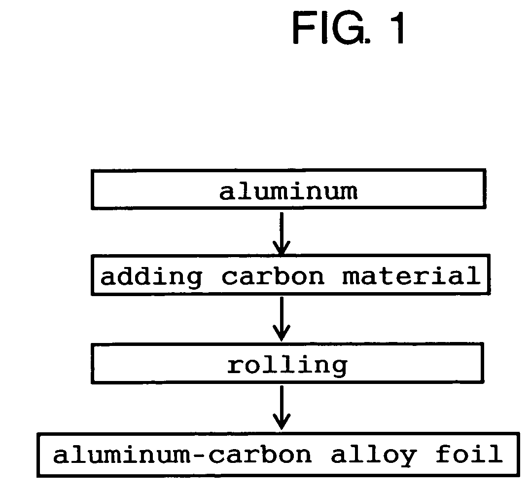
[0043]FIG. 1 is a production flowchart showing a method for manufacturing an electrode of an EDLC of a first embodiment of the present invention.

[0044]As shown in FIG. 1, first of all, an aluminum foil is prepared. The aluminum foil is coated with a carbon material containing carbon black having an average particle diameter of 0.3 μm. Then, the aluminum foil coated with the carbon material is rolled out at temperatures of not less than 300° C. to form an aluminum-carbon alloy layer with a composition of Al4C3.

[0045]The heating temperature has only to be not less than the alloying temperature. The Al4C3 alloy layer is found to have a thickness of about 1 μm by SIMS analysis. The Al4C3 alloy layer is formed with some degree of variation in stoichiometry, and the variation is conspicuous at the interface between aluminum and Al4C3.

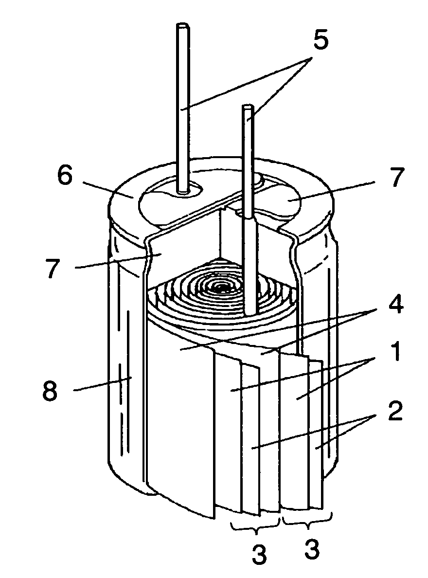
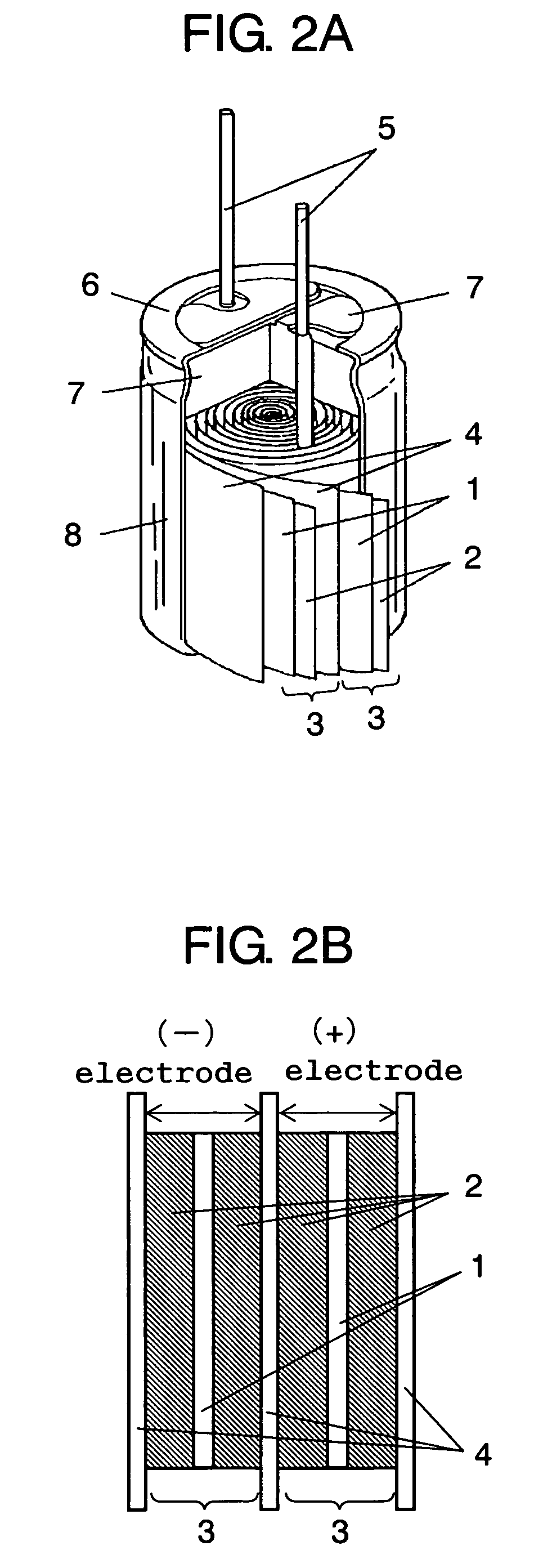
[0046]By using the aluminum electrode containing the Al4C3 alloy layer formed in this manner, a wound EDLC shown in FIGS. 2A and 2B is manufactured. In FIGS....

second exemplary embodiment

[0057]FIG. 4 is a partially broken perspective view showing a structure of an EDLC of a second embodiment of the present invention. FIG. 5 is a perspective view showing the EDLC.

[0058]In FIGS. 4 and 5, the EDLC includes case 9 made of aluminum, an electrolytic solution filled in case 9 and two electrode foils 10 made of aluminum and soaked in the electrolytic solution. Electrode foils 10 are alternately laminated with separators 11 and wound together as shown in FIG. 4. Two electrode foils 10 are connected with each of lead wires 12. Lead wires 12 are drawn out of case 9 through sealing rubber 13. Each aluminum electrode foil 10 is coated on the front and rear surfaces with aluminum fluoride 14 and further with active carbon 15 as shown in FIG. 8.

[0059]The principle of operation of the EDLC will be described as follows with reference to FIG. 6.

[0060]FIGS. 6A and 6B are sectional views of the EDLC in charging conditions and in discharging conditions, respectively. In charging conditi...

third exemplary embodiment

[0074]FIGS. 10A and 10B are sectional views showing an electrode body in an EDLC of a third embodiment of the present invention before and after the electrode body is plasma-treated, respectively. The electrode body is formed in the same manner as described in the first embodiment as follows. First, 2 μm-thick aluminum-carbon alloy layer 1a with a composition of Al4C3 is formed on the surface of collector 1 made of a 20 μm-thick aluminum foil, and then electrode layer 2 mainly composed of active carbon 2a is formed on Al4C3 alloy layer 1a. Note that electrode layer 2 mainly composed of active carbon 2a further contains conductive additive 2b and binder 2c.

[0075]The electrode body thus formed is subjected to a plasma treatment in accordance with the requirements shown in Table 2 below. In the electrode body subjected to the plasma treatment, as shown in FIG. 10B, the portion of Al4C3 alloy layer 1a that is in contact with collector 1 made of aluminum foil and active carbon 2a has no...


PUM

PropertyMeasurementUnit
voltageaaaaaaaaaa
voltageaaaaaaaaaa
particle diameteraaaaaaaaaa

Abstract

Provided are an electric double-layer capacitor which can have a reduced internal resistance and an improved withstand voltage with a simple structure, and a method for manufacturing the capacitor. The electric double-layer capacitor uses an alloy of carbon and aluminum as a material of the electrode. The electrode is formed by applying carbon to an aluminum foil and heating the aluminum foil with carbon thereon to a temperature at which the aluminum foil and the carbon are alloyed.

Description

[0001]This application is a U.S. National Phase application of PCT International Application PCT / JP2005 / 000630TECHNICAL FIELD[0002]The present invention relates to an electric double-layer capacitor (hereinafter, EDLC) used in a variety of electronic devices, a method for manufacturing the EDLC and an electronic device having the EDLC.BACKGROUND ART[0003]Japanese Patent Unexamined Publications No. H11-288849 (Document 1) and No. 2001-297952 (Document 2) disclose methods for producing an electrode metal material which can reduce the internal resistance of a capacitor. The electrode metal material is used in contact with an electrolytic solution in a capacitor such as an EDLC. These methods reduce the internal resistance of an electrode by fixing carbon particles on a valve metal such as aluminum so as to secure the electric connection between the aluminum and the active carbon on the electrode. Japanese Patent Unexamined Publication No. 2000-269095 (Document 3) discloses a method for...

Claims


Application Information

Patent Timeline
Patent Type & Authority Patents(United States)
IPC IPC(8): H01G9/00H01G9/26H01G11/22H01G11/34H01G11/66H01G11/68H01G11/70
CPCH01G9/016H01G9/155H01G11/26H01G11/32H01G11/80H01G11/82H01G11/86H01G11/38H01G11/08Y10T29/417Y02E60/13H01G11/74
Inventor KONDO, KEIICHISHIMAMOTO, HIDEKI
Owner PANASONIC CORP
Why Eureka
Try Eureka