Low complexity synchronization for wireless transmission

a low-complexity, wireless transmission technology, applied in the direction of synchronising signal speed/phase control, digital transmission, pulse technique, etc., can solve the problem of high-speed components and/or excessively complex circuits, and it is generally impractical to transmit the required sampling clock signal separate from the transmitted data signal, etc. problem, to achieve the effect of low-complexity synchronization and communication system cos

Active Publication Date: 2008-07-01
MICROCHIP TECH INC
View PDF15 Cites 25 Cited by
  • Summary
  • Abstract
  • Description
  • Claims
  • Application Information

AI Technical Summary

Benefits of technology

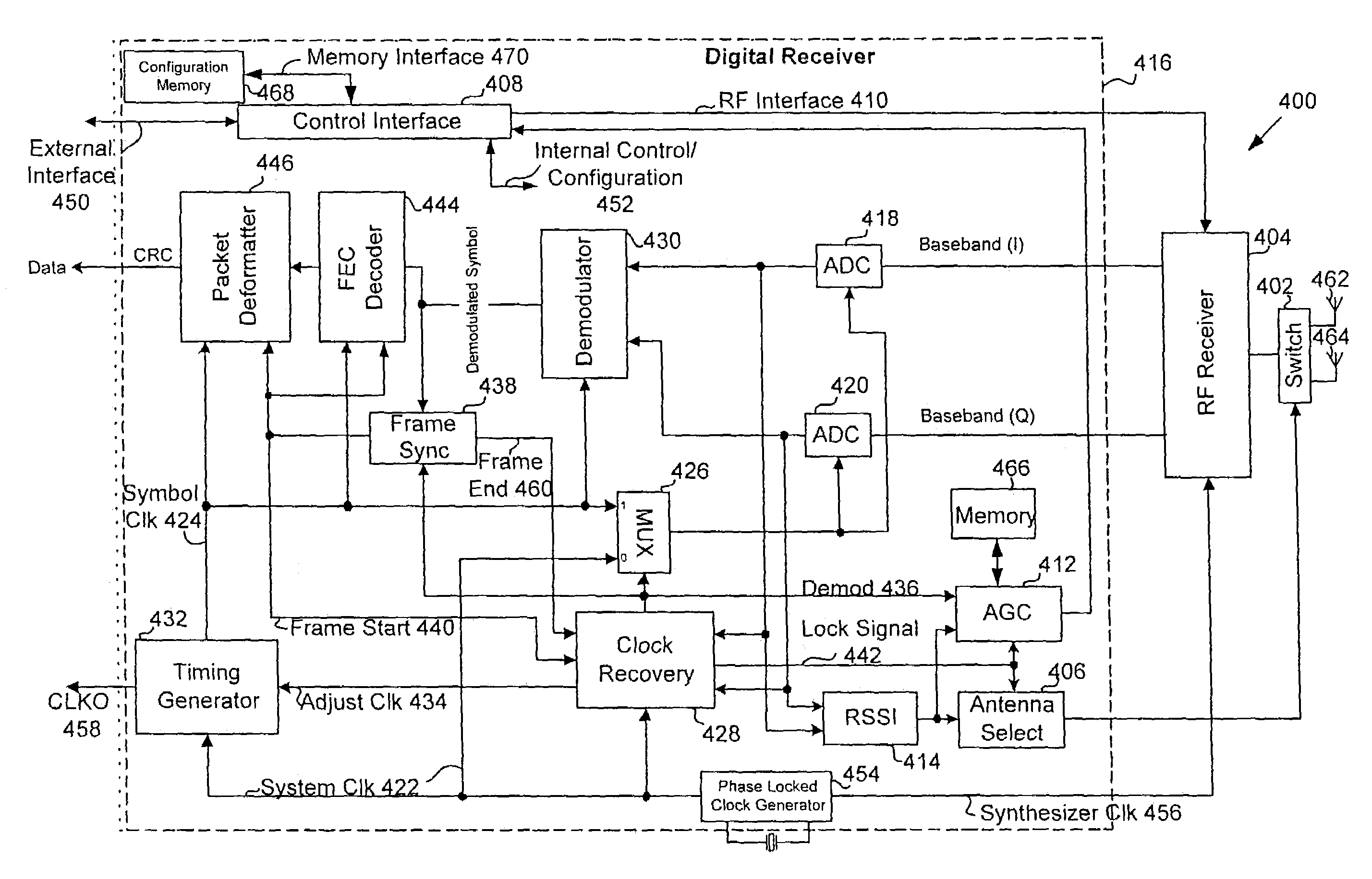
[0013]Embodiments of the present invention provide for symbol timing recovery that allows for inexpensive and low-complexity synchronization for communication systems by eliminating the need for a numerically controlled oscillator or voltage controlled oscillator. Embodiments of the present invention relate to a receiver, system and method for recovering symbol timing in a received signal by controlling a sampling device such that in-phase (I) and quadrature (Q) components of the received signal are sampled at a symbol rate.

Problems solved by technology

Due to limited bandwidth, it is generally impractical to transmit the required sampling clock signal separate from the transmitted data signal.
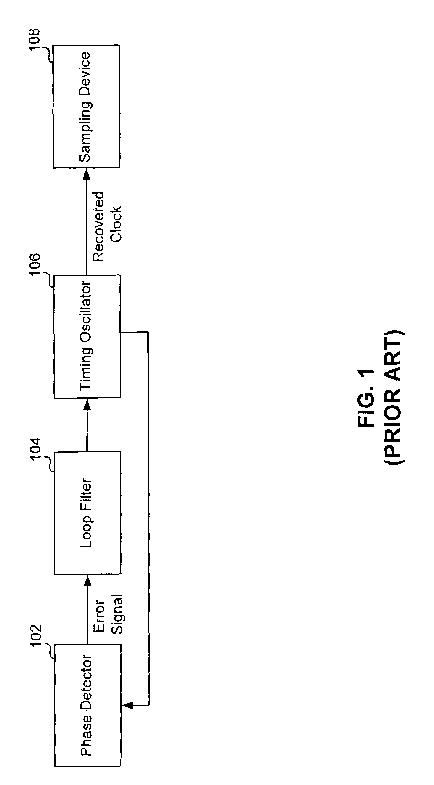
The use of these conventional timing oscillators in symbol timing recovery systems requires the use of expensive high speed components and / or the use of excessively complex circuits.
However, such a high frequency crystal oscillator is expensive.
Thus, although the NCO provides excellent resolution to provide for optimum sampling, it adds greatly to the cost of the symbol timing recovery system.
However, the PLL / crystal oscillator combination requires additional circuitry and thus adds to the complexity of the symbol timing recovery system.
Although, using of a VCO for the timing oscillator avoids any requirement of for a high speed crystal oscillator, it still requires additional circuitry and thus adds to the complexity of the symbol timing recovery system.

Method used


Image

  • Low complexity synchronization for wireless transmission
  • Low complexity synchronization for wireless transmission
  • Low complexity synchronization for wireless transmission

Examples


example listing a

[0118]

Set the VGA (GVGA) to MAX_VGA_GAINSet LNA gain (GLNA) to MAX_LNA_GAINObtain new RSSI valueif (RSSI min) {GVGA = infinity;} elseif (RSSI > Vmax) {Set VGA gain to MIN_VGA_GAIN;Obtain new RSSI valueIf (RSSI > Vmax) {Set GLNA to MIN_LNA_GAIN;Obtain new RSSI valueIf (RSSI > Vmax) {GVGA = −infinity} else {GVGA = FindGain( )};} else {GVGA = FindGain( );}}if GVGA = infinity {Total gain (Gt) = infinity;} elseif (GVGA = −infinity {Total gain (Gt) = −infinity;} else {Total gain (Gt) = GVGA + GLNA;}

[0119]The pseudo-code for the FindGain( ) function used above is shown below.

[0120]

FindGain( ) {Gmax(0) = MAX_VGA_GAIN;Gmin(0) = MIN_VGA_GAIN;G(0) = MIN_VGA_GAIN;n = 1;while ((Vmax min) && Not TIMEOUTAGC ) {if (RSSI min && G(n−1) MAX_VGA_GAIN && NotTIMEOUTAGC) {Gmin(n) = G(n−1);G(n) = (G(n−1) + Gmax(n−1)) / 2;If G(n) = = G(n−1) return (G(n) + 3Nzero);Obtain new RSSI value;n = n + 1;}if (RSSI > Vmax && G(n−1) MIN_VGA_GAIN&& NotTIMEOUTAGC) {Gmax(n) = G(n−1);G(n) = (G(n−1) + Gmin(n−1)) / 2;If G(n)...


PUM


Abstract

A receiver, system and method for providing symbol timing recovery that allows for inexpensive and low-complexity synchronization for communication systems. A receiver receives a signal including digital data in the form of packets that is transmitted from a transmitter. The receiver uses information contained in each of the packets to align a phase of the receiver clock with a phase of the transmitter clock. The receiver further controls a sampling device such that the in-phase (I) and quadrature (Q) components are sampled at an optimum sample rate and at an optimum instance of time without requiring a numerically controlled oscillator or voltage controlled oscillator.

Description

BACKGROUND OF THE INVENTION[0001]1. Field of the Invention[0002]The present invention relates generally to the field of digital communications. Specifically, the present invention relates to synchronizing digital receivers to symbol timing. More specifically, the present invention relates to recovering symbol timing in a received signal by controlling a sampling device such that in-phase (I) and quadrature (Q) components of the received signal are sampled at a symbol rate.[0003]2. Description of the Related Art[0004]The efficient functioning of modern data communications systems using bidirectional digital data communication requires clock and data recovery circuitry. The ability to regenerate binary data is an inherent advantage of transmitting information digitally as opposed to transmitting such information in analog form. However, in order for the intelligence signal to be correctly reconstructed at the receiving end, the transmitted binary data must be regenerated with the fewe...

Claims


Application Information

Patent Timeline
Patent Type & Authority Patents(United States)
IPC IPC(8): H04L27/00H04L7/033H04L7/04
CPCH04L7/042H04L7/0337
Inventor CHIEN, CHARLESCHIEN, DAVID HSUEH-CHIA
Owner MICROCHIP TECH INC
Why Eureka
Try Eureka