Dual mode hybrid electric thruster

a hybrid electric and thruster technology, applied in the field of propulsion systems, can solve the problems of large thrust of solid fuel propulsion systems, narrow range of ion propulsion applications, and low thrust of ion propulsion systems compared with chemical propulsion systems, and achieve the effect of low thrust and high thrus

Active Publication Date: 2008-07-08
THE BOEING CO
View PDF22 Cites 11 Cited by
  • Summary
  • Abstract
  • Description
  • Claims
  • Application Information

AI Technical Summary

Problems solved by technology

Unfortunately, the range of ion propulsion applications is narrowed by the fact that, although they are efficient, ion propulsion systems develop very low thrust when compared with chemical propulsion systems.
Solid fuel propulsion systems provide large amounts of thrust, but cannot be shut off once ignited.
A solid fuel engine burns from the inside out, and as a result, the cavity inside the engine is getting larger.
Liquid fuel propulsion systems typically provide less thrust per kilogram of fuel than solid fuel propulsion systems and are much more volatile.
Cold gas systems do not produce as much thrust per kilogram of fuel as liquid or solid fueled systems due to the lack of combustion.
Chemical propulsion systems are limited by the available reaction energies and thermal transfer considerations to exhaust gas velocities of a few thousand metres per second.
Typical missions therefore often utilize spacecraft carrying both thruster types at a cost and mass disadvantage.
To avoid the mass disadvantages of carrying low-efficiency fuel for (say) orbit raising from initial transfer / parking orbit to final altitude, one other prior art solution has been to suggest the application of low thrust ion engines to this orbit raising phase, but with compromise in extended periods of transportation (up to several months), with risk of Van Allen belt radiation damage amongst other concerns.
This design allows for some level of thrust control, but the resultant increase thrust is very small.

Method used


Image

  • Dual mode hybrid electric thruster
  • Dual mode hybrid electric thruster
  • Dual mode hybrid electric thruster

Examples


Embodiment Construction

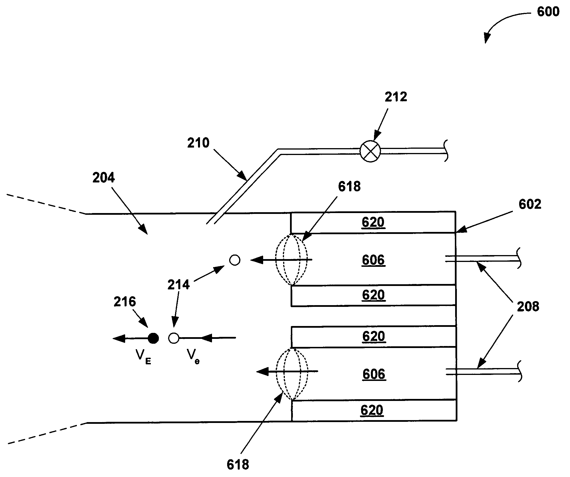
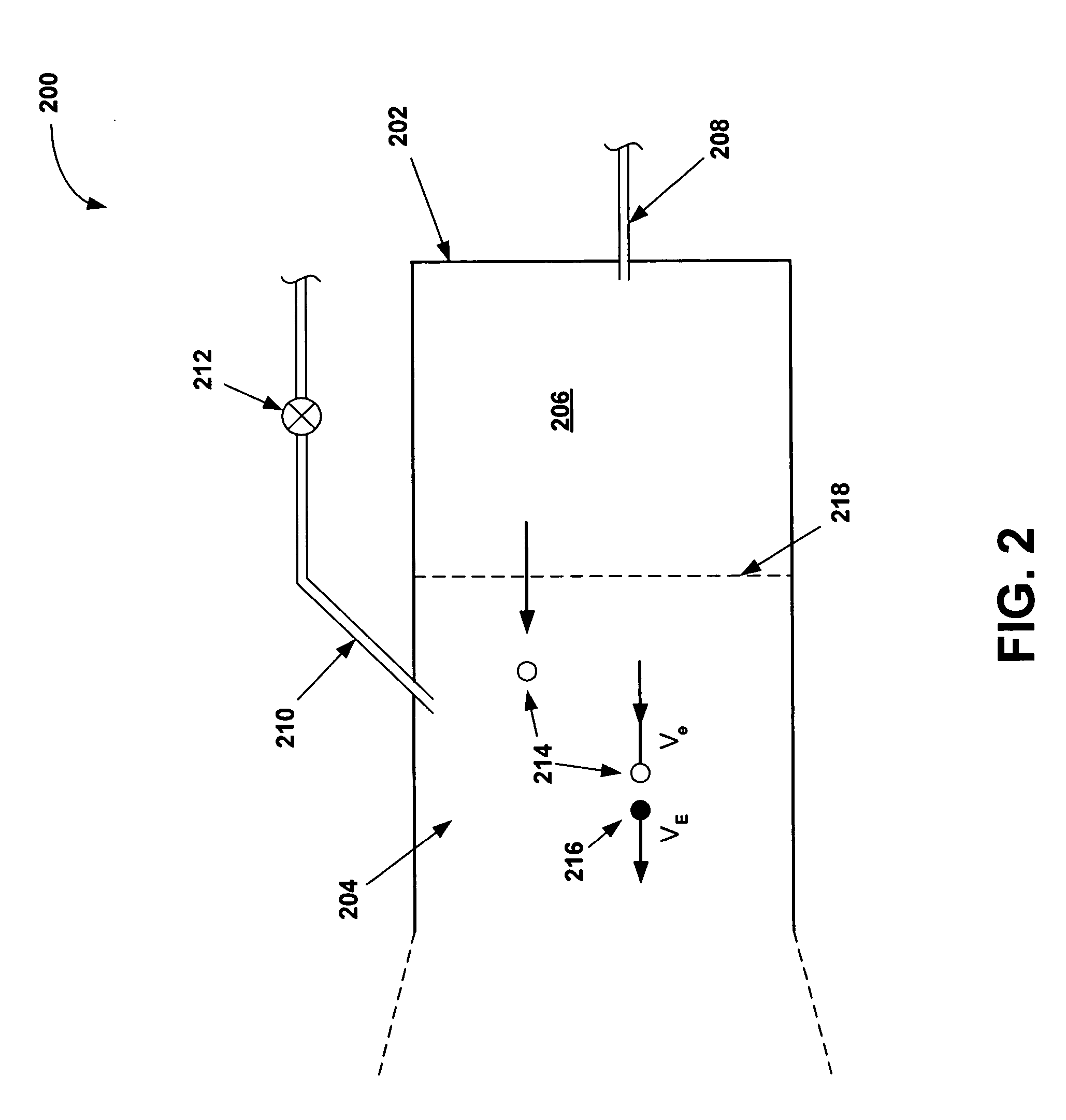
[0025]An invention is disclosed for a dual mode hybrid electric thruster. In general, embodiments of the present invention provide low thrust using ion / plasma exhaust only, and high thrust by mixing a neutral molecular gas with the ion / plasma exhaust. The new variable thrust engine can be throttleable linearly in the high thrust mode, while maintaining multi-stage thrust variation in the low thrust mode.

[0026]In the following description, numerous specific details are set forth in order to provide a thorough understanding of the present invention. It will be apparent, however, to one skilled in the art that the present invention may be practiced without some or all of these specific details. In other instances, well known process steps have not been described in detail in order not to unnecessarily obscure the present invention.

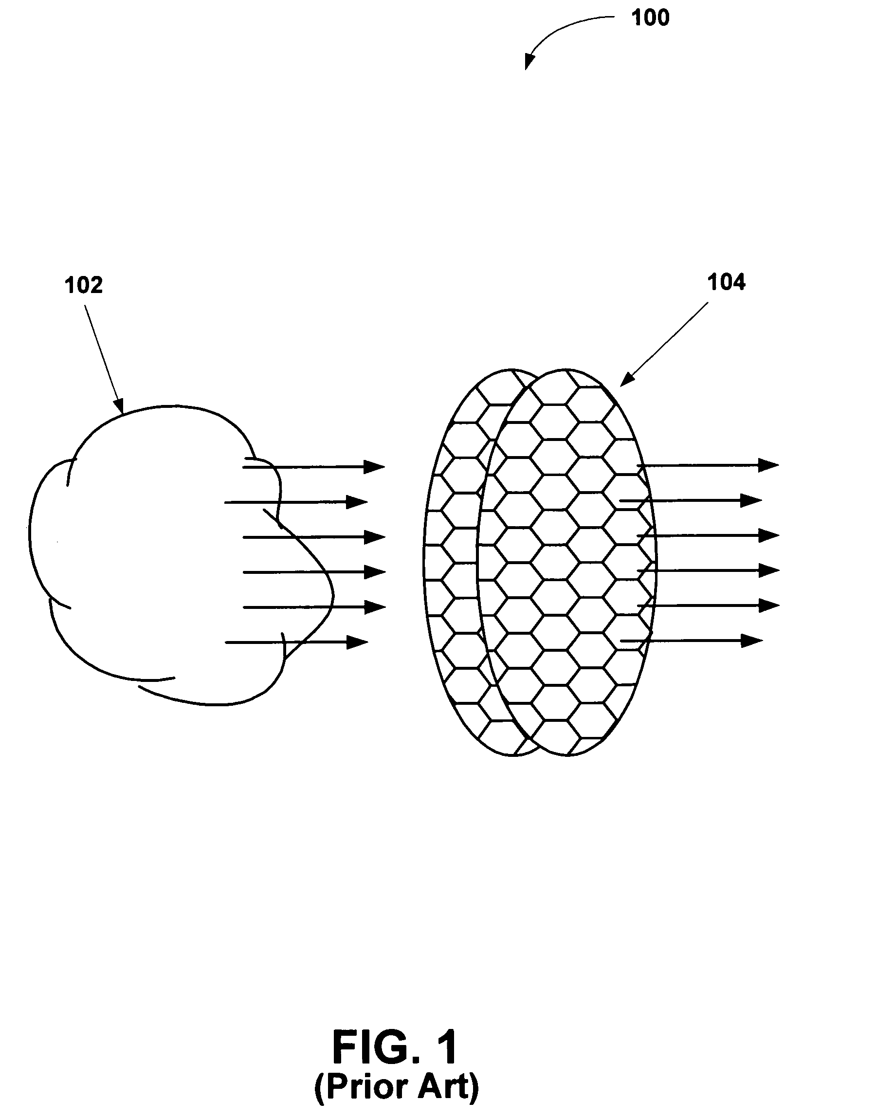
[0027]FIG. 1 was described in terms of the prior art. FIG. 2 is a schematic diagram showing a dual mode hybrid electric thruster 200 in accordance with an em...


PUM


Abstract

An invention is provided for a dual mode hybrid electric thruster propulsion system. The dual mode hybrid electric thruster provides low thrust using ion / plasma exhaust only, and high thrust by mixing a neutral molecular gas with the ion / plasma exhaust. The dual mode hybrid electric thruster includes a main propellant duct defining a main propellant intake. Coupled to the main propellant duct is an accelerating element, which includes an ionization chamber and an exhaust output. In addition, a momentum exchange zone is located at the exhaust output of the accelerating element. The momentum exchange zone includes a secondary propellant duct defining a secondary propellant intake, which provides a secondary propellant into the momentum exchange zone. In high-thrust mode, the momentum exchange zone exchanges momentum between high velocity ions from the accelerating element with atoms of the secondary propellant.

Description

BACKGROUND OF THE INVENTION[0001]1. Field of the Invention[0002]This invention relates generally to propulsion systems and more particularly to a dual mode hybrid electric thruster.[0003]2. Description of the Related Art[0004]Spacecraft such as communications satellites typically utilize electric thrusters for stationkeeping and other functions. Electric thrusters, such as ion thrusters utilize electrical power generated by the solar cells of the satellite to supply energy to a propellant to achieve the propulsion. The ion thruster also has a high specific impulse, making it an efficient engine which requires very little propellant. As a result, ion thrusters require relatively small amounts of a consumable propellant, which is an advantage over using an engine using chemical propellants.[0005]Ion propulsion generally involves employing an ionized gas accelerated electrically across charged grids to develop thrust. The electrically accelerated particles can achieve speeds of approxi...

Claims


Application Information

Patent Timeline
Patent Type & Authority Patents(United States)
IPC IPC(8): F03H1/00
CPCB64G1/405F03H1/0037F03H1/0012
Inventor ROONEY, KEVIN J.
Owner THE BOEING CO
Why Eureka
Try Eureka