Remote emissions sensing system and method incorporating spectral matching by data interpolation

a remote emission and sensing system technology, applied in the field of remote emission sensing systems, can solve the problems of inefficiency and/or inaccurate current methods for correcting for “wavelength drift” in res systems, inaccuracy in conventional systems, and inability to accurately detect the emission of a single wavelength, etc., to achieve the effect of improving spectral matching

Inactive Publication Date: 2008-07-15
ENVIROTEST SYST HLDG CORP
View PDF59 Cites 9 Cited by
  • Summary
  • Abstract
  • Description
  • Claims
  • Application Information

AI Technical Summary

Benefits of technology

[0007]One aspect of the invention relates to a system and method for correcting for “wavelength drift” in an RES system. One advantage provided by the invention includes the ability to correct for offset amounts of “wavelength drift” that are not divisible by an integer number of pixels in an optical detector used in the RES system. For example, such offset amounts may include offset amounts that are smaller than a single pixel, and / or other fractional pixel offset amounts (e.g., 1½ pixels, 2¼ pixels, etc.). Correction of fractional pixel offset amounts may enhance spectral matching, enable substantially continuous calibration of an RES system, and provide other benefits.

Problems solved by technology

However, one source of inaccuracy in conventional systems may include a phenomenon known as “wavelength drift.”“Wavelength drift” is a phenomenon in which the spectrum of spatially arranged electromagnetic radiation incident on the sensor may wander such that the wavelength ranges of the electromagnetic radiation received by the sensor pixels vary over time.
For example, ambient conditions (e.g., temperature, pressure, etc.), mechanical instability, and / or other factors may cause “wavelength drift” within the detector.
Current methods for correcting for “wavelength drift” in RES systems tend to be inefficient and / or inaccurate.
Such a method for calibrating for “wavelength drift” may be inefficient because the introduction of the mixture of gases of known concentrations into the optical path may require additional system capabilities (e.g., positioning a gas cell, providing a “puff” of gas, etc.).
This method may also be inaccurate because it only enables calibration for “wavelength drift” that is at least as large as on pixel of the sensor array.
In other words, current solutions for correcting for “wavelength drift” may not enable for corrections of “wavelength drift” smaller than a single pixel.
These and other drawbacks exist with known methods for correcting for “wavelength drift” in RES systems.

Method used


Image

  • Remote emissions sensing system and method incorporating spectral matching by data interpolation
  • Remote emissions sensing system and method incorporating spectral matching by data interpolation
  • Remote emissions sensing system and method incorporating spectral matching by data interpolation

Examples


Embodiment Construction

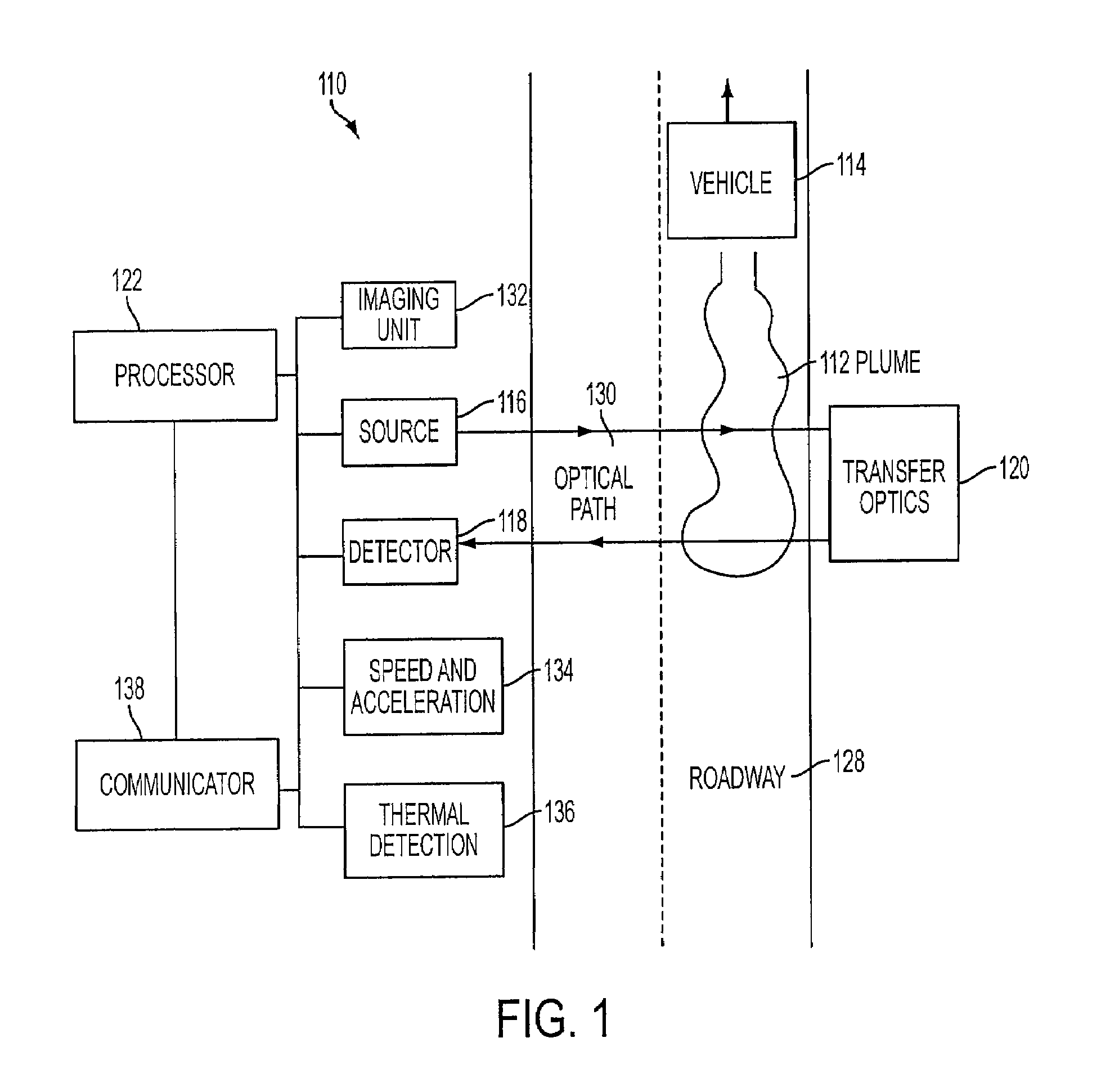
[0024]Prior to describing the RES system and method incorporating spectral matching by data interpolation, a description of an exemplary RES system for remotely monitoring the exhaust gas composition of motor vehicles on a roadway or driving surface at a given test site (or in the “field”) under various operating conditions will first be provided. The calibration / correction methods disclosed herein can be used with this or other system configurations. Embodiments of the invention may include all or some of the RES system components as described below, or other components.

[0025]FIG. 1 illustrates a RES system 110 according to one or more implementations of the invention. RES system 110 measures emissions in an exhaust plume 112 (from a motor vehicle 114) in an optical (or measurement) path 130 on a roadway 128. Roadway 128 may comprise a single or multi-lane roadway, or any other roadway or driving surface suitable for the safe passage of vehicle 114 under various operating condition...


PUM

PropertyMeasurementUnit
wavelengthaaaaaaaaaa
concentrationaaaaaaaaaa
wavelength absorption bandaaaaaaaaaa

Abstract

A system and method for correcting for “wavelength drift” in an RES system. One advantage provided by the invention includes the ability to correct for offset amounts of “wavelength drift” that are not divisible by an integer number of pixels (e.g., fraction pixel offset amounts) in an optical detector used in the RES system. Correction of fractional pixel offset amounts may enhance spectral matching, enable substantially continuous calibration of an RES system, and / or other benefits.

Description

FIELD OF THE INVENTION[0001]The invention relates generally to remote emissions sensing systems, and more particularly to a remote emissions sensing system and method incorporating spectral matching by data interpolation to correct for “wavelength drift” in an optical detector.BACKGROUND OF THE INVENTION[0002]Remote emissions sensing systems (hereinafter “RES systems”) for detecting the concentrations of one or more gases in an exhaust plume of a motor vehicle are known. Conventional systems are configured to direct electromagnetic radiation through an exhaust plume of a passing vehicle, and monitor the intensity of the electromagnetic radiation received at a detector after the electromagnetic radiation has passed through the plume. As the electromagnetic radiation passes through the plume, gases within the plume may absorb the radiation within specific wavelength absorption bands that correspond to the particular gases present. Based on the amount of light transmitted and / or absorb...

Claims


Application Information

Patent Timeline
Patent Type & Authority Patents(United States)
IPC IPC(8): G01N21/31G01J3/42
CPCG01J3/02G01J3/0264G01N21/274G01J3/28G01N2021/1793G01N21/33
Inventor STEDMAN, DONALD H.
Owner ENVIROTEST SYST HLDG CORP
Why Eureka
Try Eureka