Asynchronous sampling rate converter and method for audio DAC

Active Publication Date: 2008-08-05
TEXAS INSTR INC
View PDF6 Cites 23 Cited by
  • Summary
  • Abstract
  • Description
  • Claims
  • Application Information

AI Technical Summary

Benefits of technology

[0017]It is an object of the invention to provide a way to more easily utilize audio DACs without requiring the opera

Problems solved by technology

In some applications, it is difficult to provide analog DAC clock signals that meet the foregoing requirements.
That is, a low jitter clock signal having a frequency related to the audio sampling rate is not conveniently available in some applications.
In this case, even though the nomina

Method used


Image

  • Asynchronous sampling rate converter and method for audio DAC
  • Asynchronous sampling rate converter and method for audio DAC
  • Asynchronous sampling rate converter and method for audio DAC

Examples


Embodiment Construction

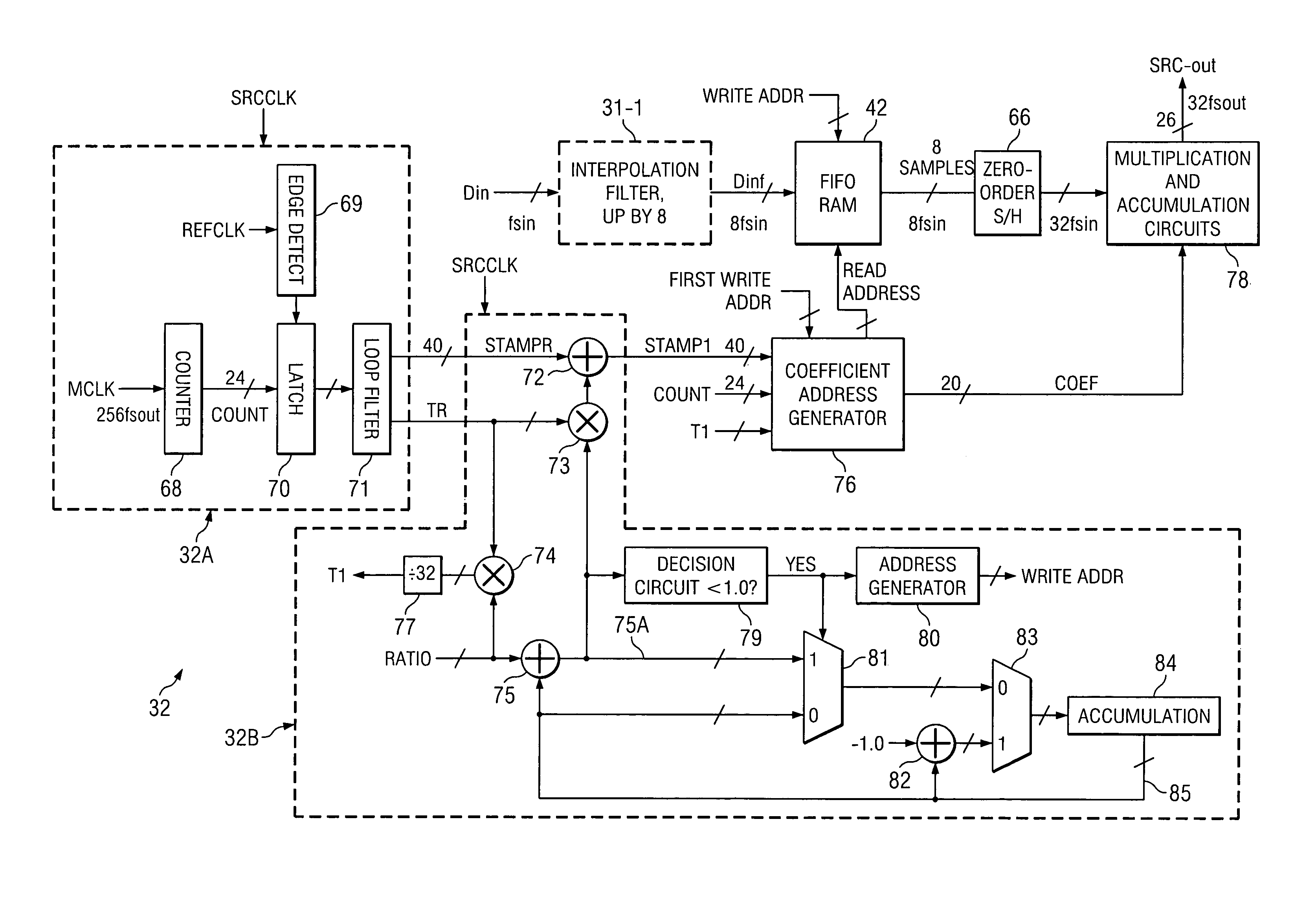
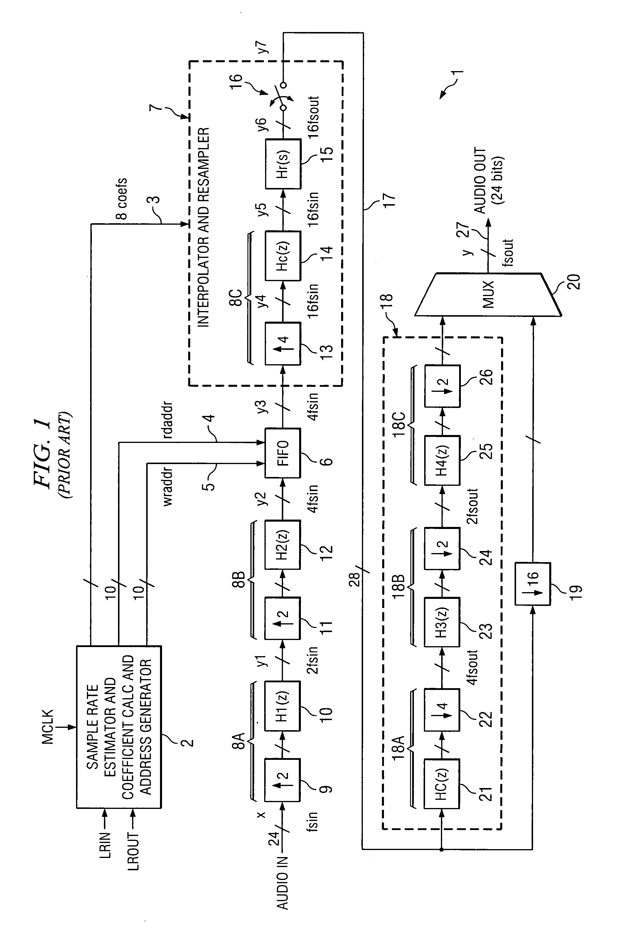
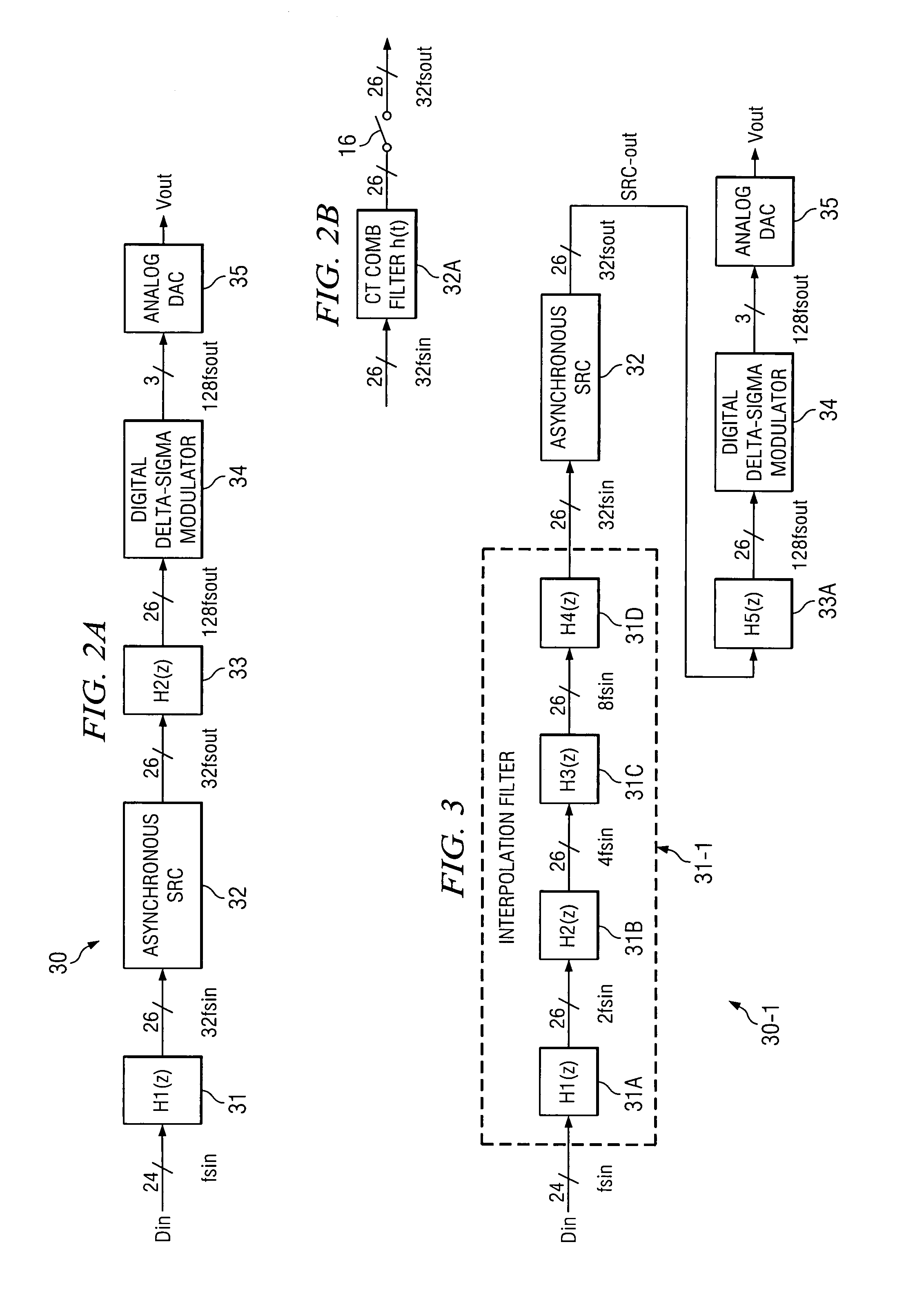
[0042]FIG. 2A shows an “audio DAC”30 including an interpolation circuit 31 having a transfer characteristic H1(z). To reduce the complexity of the asynchronous sampling rate converter (SRC) 32 thereof, the audio input data is interpolated before the sampling rate conversion. Interpolation filter 31 up-samples the 24-bit digital input data signal Din from an audio input sample rate fsin to produce a 26-bit signal with a sample rate of 32fsin, z being the operator of a z transforms for discrete-time systems and signals. The output of interpolation circuit 31 is applied to the input of asynchronous SRC 32, which as subsequently explained, is clocked by a reference clock signal (e.g., the REFCLK signal in subsequently described FIGS. 4A-D and 5) which can be derived from a 32.768 kHz clock signal SLEEPCLK commonly used in cell phones. SRC 32 also is clocked in response to a clock signal OSCLK generated by an on-chip oscillator 63 (shown in FIG. 5). SRC 32 converts its input signal sampl...


PUM


Abstract

A sample rate converter suitable for use in an audio DAC includes a first estimating circuit (32A) generating first (TR) and second (STAMPR) signals synchronized to an asynchronous clock (MCLK) and representing the period and edge arrival times, respectively, of a reference clock (REFCLK). A second estimating circuit (32B) operates on the first and second signals to generate third (T1) and fourth (STAMP1) signals representing an input sample rate (32fsin) and arrival times of input data samples, respectively, which are applied to a coefficient and address generator (76) to generate read addresses and coefficients input to a FIFO memory (42) receiving digital input data at the input sample rate and a multiplication/accumulation circuit (78) receiving data from the FIFO memory. The multiplication/accumulation circuit produces an output signal (SRC-out) synchronized to the asynchronous clock at an output sample rate (32fsout).

Description

BACKGROUND OF THE INVENTION[0001]The present invention relates generally to use of sample rate converters, and more particularly to use of sample rate converters in audio digital to analog converters (“audio DACs”) in which the audio DAC is not required to be locked in synchronization with the sampling rate of the audio input data.[0002]An audio DAC ordinarily consists of two parts, including a digital signal processing circuit which interpolates (and sometimes performs other processing on) the incoming audio data. The interpolated data may be processed by a digital delta-sigma modulator, the output of which typically is provided as an input to an analog DAC. In conventional audio DACs, the audio data is interpolated by multi-stage interpolation filters and then is fed into a digital delta-sigma modulator. The digital delta-sigma modulator is used to reduce the audio data word width and push quantization noise out of the audio band to reduce distortion caused by nonlinearity of an a...

Claims


Application Information

Patent Timeline
IPC IPC(8): H03M7/00
CPCH03H17/0628H03H17/0614
Inventor YU, SHAWN XIANGGANGSCULLEY, TERRY L.
Owner TEXAS INSTR INC
Why Eureka
Try Eureka